
Wooden CNC Touch Probe

diy-touch-probe

[Gary] sent a few pictures of his latest project our way via Flickr, which we thought a few of you CNC owners might be interested in. He has been working with his CNC machine a lot lately and decided it was about time he built a touch probe for his rig.

His initial goal was to use the touch probe to ensure his CNC table was perfectly level, but we’re thinking it will be helpful for a lot of different projects in the future. [Gary] says he was really looking to put together a proof of concept device, but that things worked out so well he had to share.

His probe seems to work very well, even without the fit and finish of others we’ve seen in the past. The body of the probe itself was built using several layers of quarter inch plywood, housing three sets of two screws. The screws are wired together in order to form a closed circuit when the brass probe is inserted. When the probe makes contact with a solid object, the circuit is broken, and the coordinates of the probe’s head are recorded.

Though [Gary] admits that he was not super careful when it came to building the probe, we think the results speak for themselves. For a first iteration its scanning abilities are pretty impressive – we can’t wait to see version 2.
Wireless Door Alarms Protect Your Stuff From Afar

wireless-shed-alarm

[Webby] had a friend named [Steve], and as the story goes [Steve] had a few storage sheds on his property that were prone to break-ins.

While the doors were all fitted with a lock, wooden doors are only so strong, and are easy fodder for intruders bearing crowbars and the like. [Steve] was looking for a good way to know when people were poking their heads where they don’t belong, so he rigged up a set of simple alarms that let him know when it’s time to break out the shotgun.

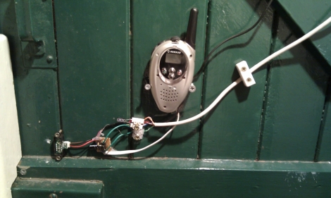
On each of the shed doors, he installed a small IR proximity sensor wired up to a PIC12F675 microcontroller. The PIC is is connected to the “call” button a medium range wireless radio, so that whenever the IR sensor detects that the door is ajar, the PIC triggers an alert on the base unit.

The solution is simple, which we figure also makes it pretty reliable – nice job!

A “Jukebox” In A Bell Jar

jukebox in bell jar

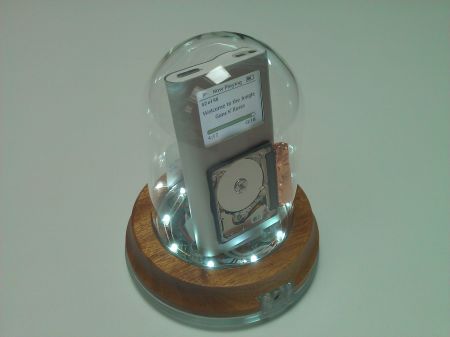
[Tim] wrote in to tell us about his Mark III hard drive in a bell jar, and we were quite impressed! The principle of using a bell jar to protect the hard drive inside so the world can see it spinning is really a cool idea, but his execution of this project is excellent. It was reportedly so good that an unnamed college actually asked him to build one of his drive displays for them.

The Mark III is an excellent build, and the little hard drive has been swapped to the front of it for better visualisation. The disadvantage of the iPod Mini used for the Mark III build is that it actually buffers enough so that the read head doesn’t have to spin during the entire song.  Because of this, we thought that his first build, nicknamed [pink], was even more interesting, if ever so slightly less refined. By many of our hacking standards though, both are incredibly finished works of art!

Both these builds feature a plethora of LEDs to keep you entertained, and can be seen demonstrated after the break! Continue reading “A “Jukebox” In A Bell Jar” →

Print In Chocolate, Sugar, And Clay With A Universal Paste Extruder

With a glut of Easter candy acquired over the last week, you might be thinking what to do with mountains of chocolate and other sugary delights. How about sending them through a 3D printer with [RichRap]’s universal paste extruder?

[RichRap]’s extruder uses a common 10cc syringes slowly squeezed by an off-the-shelf stepper motor. Chocolate wasn’t the only goal for this build;  [RichRap] also tested out cake icing, corn chip dough, muffin and sponge cake batter with his new toy. The most interesting paste in our humble opinion is porcelain ceramic clay. [RichRap] was able to make some very nice 3D printed greenware, but we’ll withhold our judgement until the ceramic parts are fired later this week.

After the break you can check out the introduction video for the Universal Paste Extruder, as well as a quick glimpse of [RichRap]’s very cool porcelain clay prints. We’re very interested in the ceramics printed with this extruder, if only for printing reprap parts that will be exposed to plastic-melting temperatures.  Of course, all the files to build your own paste extruder are up on Thingiverse.

Tip ‘o the hat to [Josef Prusa] for sending this one in.

Continue reading “Print In Chocolate, Sugar, And Clay With A Universal Paste Extruder” →

Playing Chiptunes With A YM2149 And Optimizing An Arduino

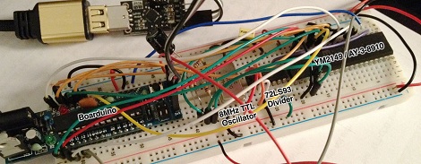
[Oryx] grew up with the bleeps and bloops of an Atari ST, so it comes as no surprise he would want to relish in his nostalgia by playing with the YM2149 sound generator he recently picked up on eBay. Like most of us, [Oryx] went to his old standby, the Arduino, when it came to connect this bare chip to his computer. The first circuit didn’t work, so after a lot of poking around the firmware, [Oryx] discovered the benefits of hand-optimizing software.

There are a lot of sound files available for the YM2149 floating around on the Internet. These files are just dumps of the 16 registers at 50Hz, so it’s very easy to send these from a computer to an Arduino over a serial connection. Unfortunately, when [Oryx] got his breadboard set up nothing happened. After breaking out the ‘scope, he discovered the Arduino was switching pins 100 times slower than the YM2149 data sheet called for.

[Oryx] remembered seeing a great blog post going over the speed at which the digitalWrite() function changes pin states. We’ve seen this before, and the fastest way to change pin states on the Arduino is with the ugly bitwise manipulation. After changing a few lines of code, [Oryx] was switching two pins nearly simultaneously.

Now that the YM2149 chip is working correctly, [Oryx] is planning to make a MIDI synth out of his project. You can get an idea of how that will sound with the demo video he put up after the break.

Continue reading “Playing Chiptunes With A YM2149 And Optimizing An Arduino” →

UPS With Dead Batteries Reborn As A Whole-house Power Backup

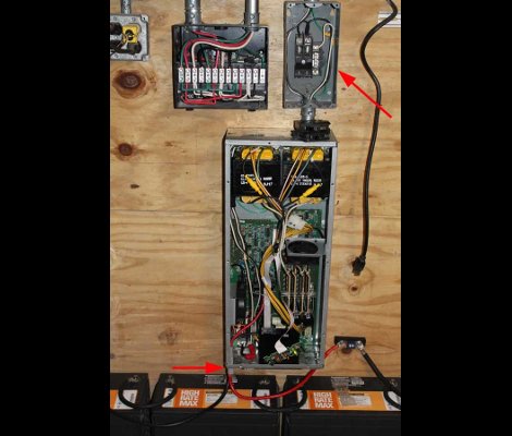
[Woodporterhouse] must deal with regular power black outs in his area. He recently converted a rack-mount uninterruptible power supply to feed a portion of his mains wiring. This one is not to be missed, since he did such a great job on the project, and  an equally remarkable job of documenting it. It’s one of the best examples we’ve seen of how to use Imgur as a project log.

The UPS still needs to have a case, but it doesn’t need room for batteries as he’s going to use a series of high-end sealed lead-acid batteries. So he cut down the enclosure to about half of the original size. That’s it mounted just above the new batteries. For this to work you need some type of transfer switch which can automatically patch between incoming line voltage, and the battery backup. He already had one of these switches in place for use with a generator, that’s it in the upper left. The entire system powers a sub-panel responsible for his essential circuits — the electronics in the home and a few lighting circuits (we’d assume this includes utilities like the refrigerator).

One really great feature that the reused UPS brings to the project is a monitoring card with a NIC. This way he can check the server to see if the UPS is being used, and how much of the 14 battery life remains.

[Thanks Ross via Reddit]

Resizable ARM Dev Board; Just Take Some Off The Top

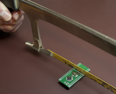
[Bob Alexander’s] most recent project is a hack saw resizable ARM breakout board. He wanted to start using more ARM microcontrollers in his projects and went for a breadboard friendly design. It uses a 40-pin dip package, but if you need the horsepower but not the I/O you can literally cut it down to size. We might recommend grabbing some tin snips, which can cut through a PCB like butter, but to each his own.

The board is based around an STM32 chip. You’ll find a crystal oscillator for the system clock, and a clock crystal if you need it. On the other side of the chip he included a footprint for a voltage regulator. This setup provides a remarkable range of input voltages, accepting from 2 to 3.6 volts without the regulator, and up to 16 volts if the regulator is present. He designed a package footprint that can be easily bridged if there’s no SMD part there. Just make sure you insulate that pad if you are using one with a conductor on the bottom. He explains this in detail in his writeup.

You’ll need a programmer to work with the board. He uses an STM32 Discovery Board for this but there are quite a few other options out there too.