Super VMW CPU Meter

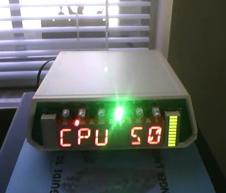
After many delays, restarts, and years, [Vince ] has finally finished his Super VMW CPU Meter. Featuring six alphanumeric red led displays, two 10 segment bar graphs, twelve red LEDs, and six color LEDs its got plenty of “screen” space to show all sorts of useful information.

Electrically its driven by four SAA1064 LED driver chips attached to an i2c bus which is banged by a PC’s parallel port and driven by software in linux. The software allows you to build displays for what ever application you may want, and even includes a color ASCII output so you can see what it will look like before you even have hardware.

Four examples are given, one is a cpu meter which uses the bar graph displays to show load per core. Another uses the bar graphs as a VU meter for your music while displaying the song’s information. There is a clock in all the normal formats + UNIX time, and some scrolling text demos.

Construction gets a little odd as overhang of chips and connectors was not really taken into account so some “lofting” was needed to raise the trouble spots above the rest of the board. It is not something we would want to do, but a handy trick if we are ever faced with that situation.

Join us after the break to see this wild light show in action. Continue reading “Super VMW CPU Meter”

PIC-based Ham Radio Autotuner

cw_autotuner

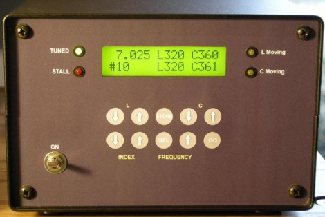
A few years back, [Floyd, K8AC] built a high frequency autotuner as an addition to his Ham radio setup. Based off a design he saw in QST magazine back in the early ’90s, he has been using the tuner almost daily for the last few years, on both the 3.5 MHz and 7 MHz bands.

Built into the wall in his radio room, it is a pretty impressive sight. His “L” circuit is controlled by a pair of mechanically coupled inductors which are driven in concert by a pair of two-way motors. The positioning of the C and L components are monitored by a PIC controller which stores the tuning data for up to 30 predefined frequencies. A couple of button presses on his controller’s front end sends the tuner into action, dialing in his unit’s inductors and capacitor to their proper settings. The PIC monitors the tuner’s progress, informing him when the proper frequency has been tuned in, or if the frequency can not be set, indicating issues with the equipment.

His setup has undergone several revisions over the years, with the most recent iteration being the most automated of the bunch. Check out his site for plenty more details, or keep an ear out for [K8AC] on 40 or 80 meters.

[Thanks, Rich V]

Circuit Building With A Hammer And Nails

real_breadboarding

[Collin Cunningham] over at Make recently wrapped up another edition of “Collin’s Lab” – this time around, the subject is breadboards. He starts off by discussing a common solderless breadboard, something you are no doubt familiar with. What you might not know however is how breadboards got their name.

Way back when, before there was a RadioShack in every strip mall across the country, fancy prototyping supplies like your solderless breadboard did not exist. Amateur radio operators would prototype circuits on wooden boards, often using whatever was around as a substrate. Many times, this meant that the family’s cutting board ended up as a makeshift prototyping station.

One popular method of building circuits was to drive small nails into the breadboard, using wire wrapping to connect things together. [Collin] demonstrates this technique in the video, constructing a simple LED flasher circuit.

He says that the process works decently enough, and was kind of fun to do. He does mention however that building any sort of circuit requiring an IC would likely be out of the question.

If you have a few minutes to spare, check out the video embedded below – [Collin’s] take on technology is quirky and entertaining as always.

Continue reading “Circuit Building With A Hammer And Nails”

Building An Augmented Reality Display Using Obsolete Technology

slideprojector_augmented_reality

Augmented reality might be all the rage these days, but when you take a closer look at the technology, you will find that these sorts of optical illusions are not new at all.

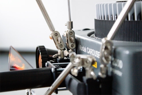
Artist [Sebastian Schmieg] was pondering augmented reality for a bit and decided he could replicate the effect using old and obsolete technology. His creation, called “81 Points of View”, uses an old Kodak slide projector and an elaborate mechanical setup to simulate the effect.

The slide projector resides on a platform that can be rotated around its center in 81 steps. After each movement, the mechanism swaps out the current slide, selecting the next image depending on which direction the user turns. The resulting effect is similar to the implementations of augmented reality you might see today, with a 3d visualization superimposed on the surrounding room.

The concept dates back all the way to the 1860’s, when [John Pepper] first demonstrated the technique. Using mirrors and panes of glass, he was able to project translucent images in front of his audience, which is the same idea [Sebastian] uses in his project. You are likely quite familiar with the effect, if you have ever visited the Haunted Mansion at a Disney theme park.

It’s a neat project, though the resultant augmented reality display is obviously not quite as smooth as you would see from a smartphone. Either way, it is definitely worth checking out. Keep reading to see a video of the project in action.

Continue reading “Building An Augmented Reality Display Using Obsolete Technology”

15-digit Nixie Clock Contains Mostly Non-useful Information

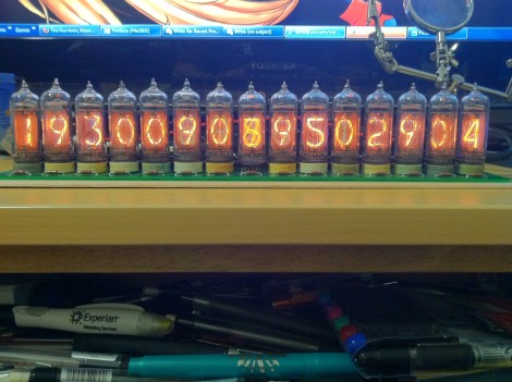
[Jarek Lupinski] is at it again, this time building a clock using 15 Nixie tubes. Just look at the time…. wait, how do you read this now? It’s not seconds since the epoch, but an homage to a very expensive New York City art piece. [Jarek] took his inspiration from the Metronome art installation in Union Square.

We hadn’t heard of it before and were shocked to learn that this art was commissioned at $4.2 million. It belches steam and confuses passersby with its cryptic fifteen digits. It seems that the eight digits on the left mark the current time – two digits for hours, two for minutes, two for seconds, and the final digit for hundreths of a second. The seven remaining digits count down the time left in the day. So when you watch it, you see the significant digits of the display increasing, and the insignificant half decreasing.

The Nixie version rests snuggly on a 15″x4″ PCB. We’re sure it doesn’t number in the millions, but that couldn’t have been cheap to have manufactured. Each tube has its own driver chip, removing the need for multiplexing. An ATmega168 controls the clock (along with some shift registers to expand the I/O count), reading time from a DS1307 RTC chip. It looks fancy, but where’s the belching smoke on this version?

Baking Pan Tube Amp Sounds Better Than You’d Expect

baking_pan_tube_amp

A few years back, [Gio] decided to try his hand at building a couple of tube amplifiers.

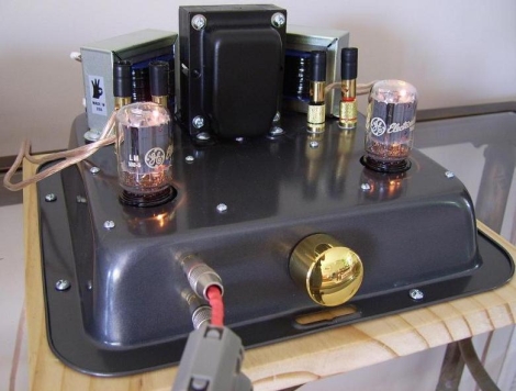
The first amp was more of an experiment to see how well a DIY single-ended tube amp would sound. The amp is based off the 6T9 design created by Spare Time Gizmos, and incorporates a pair of 6T9 vacuum tubes, hence the name.  He wired things up in an afternoon, then got busy drilling holes in a baking pan, where he mounted the amp. Bear with us for a second, it’s not as bad as it sounds. The amp actually looks pretty good mounted in the dark black steel, and this sort of enclosure is far cheaper than most DIY amp enclosures. He says that he was sure to be extra careful in isolating all of the electronic components from the metal chassis.

The second amp was built to test the performance differences between Pentode-mode and Ultra-Linear mode configurations. While both amps share a substantial amount of the same components, his UL amp benefits from slightly better capacitors and an uprated power supply, not to mention a more conventional case.

Both amps sound great, according to [Gio], but should be paired with efficient speakers for the best experience. He does note that the ultra-linear amp is the better choice, mounting options aside.

[Thanks, Philippe]

[via RetroThing]

AVR HVSP On A Tiny Breadboard

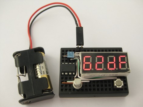
AVR chips are convenient because you can program them in circuit at their operating voltage. That is, unless you screw up the fuse settings and they’ll no longer listen to an In System Programmer. If you find yourself facing this problem, just build this circuit on a breadboard and ‘unbrick’ by holding down the button.

The circuit seen above is a High Voltage Serial Programmer. This is one of two high voltage protocols used by AVR chips; HVSP is for chips that don’t have enough pins to use High Voltage Parallel Programming. This rendition uses a 12V power source, which is the level necessary for the high voltage method. A 7805 linear regulator joins the mix to provide operational voltage, along with one transistor, an ATtiny2313 to control the circuit, a four-digit 7-segment display for feedback, and one button for control.

Watch the video after the break to see an ATtiny13 programmed to disable the reset pin using a breadboarded programmer. That chip is then easily rescued, having been automatically recognized by using its device signature.

Continue reading “AVR HVSP On A Tiny Breadboard”