Alternate Keyboard Layouts – For Geekiness And Other Reasons

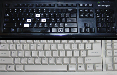
[BiOzZ] wanted to try a different keyboard layout than the ubiquitous Qwerty, so he grabbed an old keyboard and converted it to the Dvorak setup. This was accomplished by first popping off all of the keys from the black keyboard seen above, and boy did he find a mess underneath. It was nothing that a trip through the dishwasher (for the case only) wouldn’t fix, and the next step was to replace the keys in a different order. He found that a couple of them wouldn’t just go back in a different place, but had to be rotated 90 degrees to fit. Not a huge problem, you can see that he overcame the visual speedbump of letters facing the wrong way by adding his own letter labels. From there he walks us through the process of getting Windows to switch to the Dvorak layout.

I went through a similar process at the end of last year. I was experiencing a lot of pain in my hands from my prolific feature writing here at Hackaday so I chose to try out the Colemak keyboard. The white keyboard above is the one I repurposed using that layout. I found it quite easy to switch between two keyboard layouts using Ubuntu. After you’ve set it up in the keyboards dialog a layout icon appears on the panel. It wasn’t hard to pick the new key locations up, but it did reduce my typing speed by a factor of 8. In the end I found that adjusting my chair height and keeping my hands warm did the trick and I’m back on the Qwerty where I belong.
Blu-ray Laser Plotter Writes On Glow-in-the-dark Screen

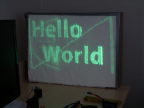
This laser display is persistent thanks to a glow-in-the-dark screen. [Daniel] built it using a Blu-ray laser diode. As the laser dot traverses the screen, it charges the phosphors in the glow material, which stay charged long enough to show a full image.

The laser head is simple enough, two servo motors allow for X and Y axis control. A Micro Maestro 6-channel USB servo controller from Pololu drives the motors, and switches the diode on and off. This board offers .NET control, which [Daniel] uses to feed the graphics data to the unit. Check out the video demonstration below the fold to see a few different images being plotted. It’s shot using a night-vision camera so that you can really see where the laser dot is on the display. It takes time to charge the glow material so speeding up the plotting process could actually reduce the persistent image quality.

This is yet another project that makes you use those geometry and trigonometry skills.

Continue reading “Blu-ray Laser Plotter Writes On Glow-in-the-dark Screen”

Keep Fun In Check With A Parental Count Down Timer

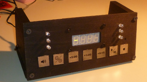
Gaming industry software engineer [Pedantite] writes in to let us know about his latest endeavor, an AVR based parental assistant timer: Good Times.   Looking for a new project that would be both useful and interesting, his wife suggested a “time out/ time’s up timer”. Like most of us [Pedantite]’s children are well studied in the arts of procrastination and mischief.  In the kids’ case this leads to time outs and break time running amok. The solution, in this case, is pretty much an advanced DIY egg timer with fun sounds.

The timer sports all of your basic countdown-timer functions including a 4 digit 7-segment LED output display, stop light style LED indicators, and controls to start/pause and stop the count down. The count down time can be input via the +5 minute, +1 minute, and +15 second buttons. There is even a happy/sad button to toggle between “time out” and “break time” modes. Two Atmel micros power the device, an AT Tiny 2313V for the capacitive touch keypad and an AT Mega 644P for the display, audio, and time measurement.  There are a lot of excellent techniques used in the build, some which we have covered here:  Four 595 Shift registers for the display; A 4 bit r2r DAC for audio output.

[Pedantite] is still in the process of writing up the project in multiple posts, and would love to know what you all want to hear about. Check out his blog for details and a quick video of the timer in action! Also, if you are interested in capacitive buttons, check out part 2 of the writeup.

Bluetooth Headset Battery Swap Keeps Going And Going…

bluetooth_headset_battery

[Reginaldo] purchased a cheap Bluetooth headset adapter, and while it worked well with all of his devices, he was disappointed to find that the battery life didn’t quite live up to the manufacturer’s claims. Advertised as capable of operating for 10 hours, he discovered that the device would typically die after only 7. He wanted more from the headset, so he took things into his own hands and replaced it with a much larger battery (Google Translation).

His goal was to keep the modifications as cheap as possible, so he repurposed a lot of items he had sitting around the house. He used a battery out of an old cell phone, with a capacity over six times greater than that of his original headset battery. He built a charging circuit using a MCP73863 microchip, specifically designed for managing Li-Ion/Li-Poly batteries. The Bluetooth headset was dismantled and repackaged in the shell of a cheap “audio amplifier” that he had on hand, along with the new battery and charging circuit. A nifty Hackaday logo was included on the outside of the new battery case, and the project was deemed complete.

[Reginaldo] reports that he is quite happy with his battery retrofit. The new power brick only takes about half an hour longer to charge, but can now be used for approximately 44 hours before requiring a recharge – not too shabby!

Everything You Need To Know About Wall Warts

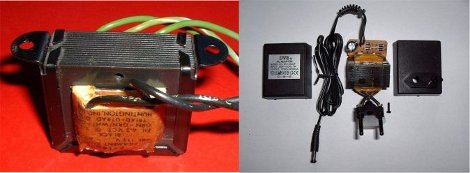
If you work with electronics at any skill level you need juice. [Jon] has a great, and clearly worded tutorial about Wall Wart Power Supplies with pretty much everything you need to know about those little black boxes hanging off of your outlets.

The whole thing starts off with the basics like transformers, rectification smoothing and regulation, then moves on to the different basic types, dedicating a page to linear, regulated and switching types, giving output performance charts under different situations.

Also included is a run-down of DC barrel jack structure so you get the right plug every time, wall wart type identification, a random sample comparison test, and a good selection of formulas to even keep the old hats reading along. Although you might want to set aside a little time at 9 pages and some Q/A in the comments, it might take a moment to read.

Reverse Engineering LED Vodka Bottle Displays

wireless_led_marquee

When [Tyler] heard about the LED matrix display that Medea Vodka was building into their bottles, he immediately wanted to get his hands on one. Who could blame him? Someone had finally combined two things we love dearly: booze and LEDs.

He struggled to find a bottle at any of his local stores for the longest time, but was absolutely stoked when he finally came across one of their reps promoting the brand while he was out shopping.

Once he got home, he pulled the display off the bottle and began poking around to see what made it tick. The display is made from a flexible PCB, and attached to the bottle with some clear elastic film. It is powered by two CR2032 batteries and controlled by a PIC16F chip, which pulls stored messages from a small Atmel EEPROM.

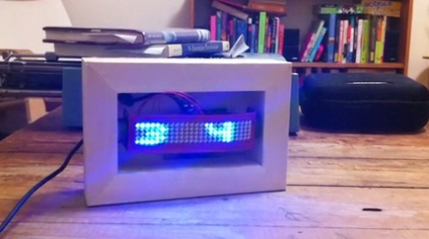
Once he figured out how to control the LED matrix, he uploaded his own fonts and added a LINX wireless module to remotely send messages to the board. He mounted it in a wooden frame and now uses it as a simple marquee display.

If you have one of these displays hanging around your house, be sure to swing by his site for schematics of his wireless interface board as well as the code he uses to drive the marquee. You can check out a video of the display in action there as well.

PID Sous-Vide Slow Cooker – Bon Appétit!

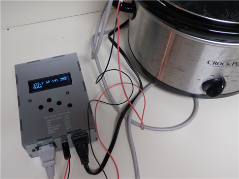
In search of a perfectly-cooked brisket, [Aaron] recently completed this DIY  PID-controlled sous-vide slow cooker. Sous-vide (French for “under vacuum”) is a cooking technique in which foods are typically vacuum-sealed and then cooked in a relatively low temperature water bath for an extended period of time. This is done to minimize temperature gradients throughout the food to ensure even cooking. Precise regulation of the water temperature is the key to ensuring that the results are exactly as desired – when cooking for many hours or days, even a few degrees discrepancy can greatly influence the final product.

A few months ago we featured a similar hack that utilized a simple switching temperature controller spliced into an extension cord.  Although probably sufficient for most aspiring “hacker-chefs”, the temperature was not as stable as it could be. The problem is that it takes time for the heat generated in the slow cooker’s heating element to reach the temperature probe (and food) suspended in the water bath.  By the time the probe reads the elevated temperature, the element is already too hot and the temperature overshoots the target. One way to mitigate this effect is to circulate the water to minimize temperature gradients, as is done in many of the expensive commercial units. In order to achieve similar results, [Aaron] instead created a PID controller that uses temperature feedback over time to precisely maintain the desired temperature and reduce any deviations resulting from outside disturbances.

The build is covered in detail and looks great in a custom acrylic enclosure. All of the board schematics, enclosure layout files, and source code are available under Creative Commons licensing at the bottom of his blog page. A good deal of time is also spent addressing the actual PID programming and tuning – something that could be useful for many different hacks requiring precise feedback control.

The end result is a professional looking control box and a slow cooker that is able to maintain temperature within 1°F even while using a DS1820 temperature sensor that is only rated as accurate to 0.5°C (0.9°F). From the pictures it looks like [Aaron] has finally achieved brisket bliss! Now the only question remaining is: what is the best setting for reheating left-over pizza?