3D Internal Structure For Better 3D Printed Objects

Makerbot is in the gutter, 3D Systems and Stratasys stock is only a shadow of their 2014 glory, but this is the best year 3D printing has ever had. Machines are now good and cheap, there’s a variety of various thermoplastic filaments, and printing useful objects – instead of just plastic trinkets – is becoming commonplace.

Gradient-Grid
The standard rectilinear infill from Slic3r

There’s one area of 3D printing that hasn’t seen as much progress, and it’s the software stack. Slicing, the process of turning a 3D object into a Gcode file for a printer has been basically the same for the last few years. Dual extrusion is still a mess, and automated bed leveling is still in its infancy.

One aspect of slicing that has been severely overlooked is infill. Obviously, you don’t want to print plastic trinkets completely solid – only the outside surface matters, and a part with 100% infill is just a waste of plastic. Different slicers have come up with different ways of filling the inside of a print, usually with a grid of squares, triangles, or hexagons.

While the most popular methods of filling in a 3D printed objects do the job of adding a little bit of strength to a print and supporting the top layers of a print, it’s not an ideal solution. The desired strength of the finished part is never taken into account, print artifacts are sometimes visible through the side of a print, and the spacing of the infill grid is completely arbitrary. You can only set a percentage of infill, and telling a slicer to make an internal support grid with 10mm spacing is impossible.

Type A Machines just changed all of this. With the release of their public beta of Cura Type A, the infill for a 3D printed part is also 3D. The dimensions of the infill are predictable, opening the door to stronger and better looking parts.

From the Type A press literature and white paper, this new type of ‘infill’ isn’t; it’s more properly referred to as ‘internal structure’, with proper dimensions between infill features. Instead of a grid of squares or triangles stacked one layer on top of each other, it’s a true structure, with the infill following the perimeter of the 3D printed object.

Generating 3D Infill

3D
Infill generated from Type A Machine’s Cura beta. Note the 3D structure of the infill.

Right now, infill is generated in a slicer by specifying a percentage. Zero percent infill means a hollow object, and 100% infill is a completely solid part. These two edge cases are easy, but anything else means the slicer must fill the part with filament in a grid of tessellating shapes, either rectangles, triangles, or hexagons. With current slicers, the dimensions of this internal structure are, for all practical purposes, random. Printing an object with 20% infill might mean a grid of squares with 5mm or 2mm spacing. Telling the slicer to infill a part with a grid of squares spaced 10mm apart is impossible.

Type A Machine’s latest Cura release changes all of this, allowing a designer to set a precise distance between rows and columns of infill. By defining infill in absolute dimensions, this allows for stronger parts using less infill.

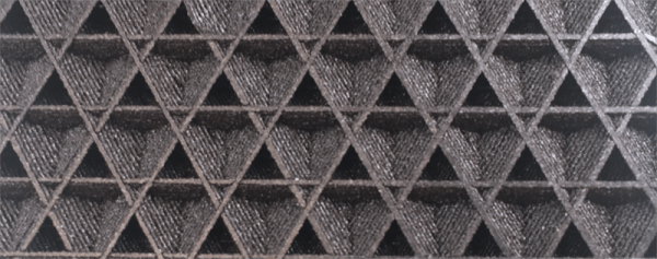
Absolute dimensioning is only one feature of the Type A Machine’s latest release of Cura. Even more exciting is the development of 3D internal structure. Instead of stacking layers of squares, triangles, or hexagons on top of each other, Type A Machine’s Cura uses an infill of cubes turned on their side. While each individual layer of infill looks like a series of triangles and irregular hexagons, when assembled into a printed 3D object, this infill forms a true 3D structure.

The closest comparison to this sort of structure is the difference between graphite and diamond. Both of these materials are made out of the same element, carbon. The physical structure of graphite is just, 1-atom-thick layers of graphene, producing a relatively weak material. Diamond, on the other hand, has a true 3D structure and is one of the hardest materials known to man. While adding 3D structure to the infill of 3D printed objects won’t make the objects any stronger, it will drastically reduce delamination, and be much more resistant to stresses in all three dimensions.

While Type A Machines has done some great work here, it does mean there’s yet another version of Cura to deal with. Type A Machine’s Cura, in addition to the LulzBot edition and the original are now the defacto standard for turning 3D objects into printed parts. Having an open source solution is great, but forking the development this much surely can’t be ideal.

3D Printing Compressed Air Tanks

Using PVC pipe as a pressure vessel for compressed air can be a fun and enjoyable hobby. It’s safe, too: while there are are reports of PVC pipe being the cause of accidents, these accidents include a black powder potato gun[1], and welding too close to a PVC pipe containing compressed air[2]. Compressed air stored in a PVC pipe is never a proximal cause in any accident, and the OSHA’s Fatality and Catastrophe Investigation Summaries bear this out; there was no industrial or occupational accident recorded in these summaries where a pressure vessel made out of PVC was the cause of any injury or death[3].

Although PVC pipe can be a perfectly safe, effective, and cheap pressure vessel for hobby applications, it’s not always the best choice. A group of students in Renens, Switzerland are building autonomous robots for the Eurobot competition, and this year’s robot uses pneumatics. That means compressed air, and that means a pressure vessel. Since just about everything else on this robot is 3D printed, they asked the obvious question. Is it possible to 3D print a tank for compressed air?

The tank for this robot would only be used up to about 4 bar (400kPa), and after a few quick calculations, the team discovered the wall thickness – even in a pressure vessel with corners – would be pretty low. The first prototype, a 40mm cube with 20% infill and a hole drilled in the side, held 6.5 bar (650kPa) for an hour. This success didn’t last, though: he second prototype, a 65x40x80mm rectangular prism printed without as much infill, exploded at 5.5bar (550kPa).

The third time’s the charm, and with filleted ribs inside the tank, the third prototype was able to hold pressure up to 6.5 bar. Of course no 3D print is perfect, and the third prototype did leak, but a bit of acrylic spray paint applied to the outer surfaces held the air in.

While it’s not as fun, easy, cheap, rewarding, or safe as using PVC pipe as a pressure vessel, the team did manage to build a 3D printed pressure vessel with a custom shape. You can’t do that very easily with round pipe. And 3D printing opens up all manner of internal structure to experiment with. We’d like to see this developed even further!

Sources: [1], [2], [3]

OzQube-1: A Tiny Australian Satellite

Over the last couple of decades we have become used to the possibility of launching a satellite into orbit no longer being the exclusive preserve of superpowers. Since the first CubeSats were launched over a decade ago a myriad others have followed, and scarcely a week passes without news of another interesting project in this area.

OzQube-1 is just such a satellite, designed for imaging of the Southern Hemisphere, and it’s the brainchild of Australian [Stuart McAndrew]. He’s posted significant details of its design: it’s a PocketQube, at 50mm cubed, an eighth the volume of a CubeSat, and its main instrument is a 2 megapixel camera with a 25mm lens. Images will be transmitted to earth as slow-scan digital video via the 70cm amateur band, the dipole antenna being made from a springy tape measure which will unfurl upon launch. Attitude control is passive, coming from a magnet aligned to ensure the camera will be pointing Earthwards as it passes over the Southern Hemisphere. The project has a little way to go yet, but working prototypes have been completed and it has a Gofundme campaign under way to help raise the money for a launch.

There are plenty of Cubesat and other small satellite builds to be found on the web, here at Hackaday we’ve covered a significant number of them. Many of them are the fruits of well-funded university departments or other entities with deep pockets, but this one comes from a lone builder from Western Australia. We like that, and we wish OzQube-1 every success!

Pong In Real Life, Mechanical Pong

[Daniel Perdomo] and two of his friends have been working on a mechanical version of Pong for the past two years. We can safely say that the final result is beautiful. It’s quite ethereal to watch the pixe–cube move back and forth on the surface.

[Daniel] has worked in computer graphics for advertising for more than 20 years. However, he notes that neither he nor his friends had any experience in mechanics or electronics when they began. Thankfully, the internet (and, presumably, sites like Hackaday) provided them with the information needed.

The pong paddles and and pixel (ball?) sit onto of a glass surface. The moving parts are constrained to the mechanics with magnets. Underneath is a construction not unlike an Etch A Sketch for moving the ball while the paddles are just on a rail with a belt. The whole assembly is made from V-groove extrusion.

Our favorite part of the build is the scroll wheel for moving the paddle back and forth. For a nice smooth movement with some mass behind it, what’s better than a hard-drive platter? They printed out an encoder wheel pattern and glued it to the surface. The electronics are all hand-made. The brains appear to be some of the larger Arduinos. The 8-bit segments, rainbow LEDs, etc were build using strips glued in place with what looks like copper foil tape connecting buses. This is definitely a labor of love.

It really must be seen to be understood. The movement is smooth, and our brains almost want to remove a dimension when watching it. As for the next steps? They are hoping to spin it up into an arcade machine business, and are looking for people with money and experience to help them take it from a one-off prototype to a product. Video after the break.

Continue reading “Pong In Real Life, Mechanical Pong”

Arc from a flyback transformer power supply

A Cornucopia Of High Voltage Sources

Having hacked away with high voltage for many years I’ve ended up using a large number of very different high voltage sources. I say sources and not power supplies because I’ve even powered a corona motor by rubbing a PVC pipe with a cotton cloth, making use of the triboelectric effect. But while the voltage from that is high, the current is too low for producing the necessary ion wind to make a lifter fly up off a tabletop. For that I use a flyback transformer and Cockcroft-Walton voltage multiplier power supply that’s plugged into a wall socket.

So yes, I have an unorthodox skillset when it comes to sourcing high voltage. It’s time I sat down and listed most of the power sources I’ve used over the years, including a bit about how they work, what their output is like and what they can be used for, as well as some idea of cost or ease of making. The order is from least powerful to most powerful so keep reading for the ones that really bite.

Triboelectric Effect

Triboelectric series table

You’ve no doubt encountered this effect. It’s how your body is charged when you rub your feet on carpet and then get a shock from touching a door knob. When you rub two specific materials together there’s a transfer of electrons from one to the other. Not just any two materials will work. To find out which materials are good to use, have a look at a triboelectric series table.

Materials that are on the positive end of the table will become positively charged when rubbed against materials on the negative end of the table. Those materials will become negatively charged. The further apart they are in the table, the stronger the charging.

Powering corona motor with triboelectricity

An example of where I’ve used this is to power the corona motor shown here. I vigorously rub a PVC pipe with a cotton cloth, and as the pipe emerges from the cloth, a sharp wire a few millimeters away takes the charge from the pipe. You can see this corona motor being powered by other power sources in the video here.

This would be considered an electrostatic power source because charge is accumulated on surfaces. Being insulating materials, that charge can’t move around.

Continue reading “A Cornucopia Of High Voltage Sources”

The Booths Of Hamvention

Hamvention was last weekend in Dayton, Ohio. Last weekend was also the Bay Area Maker Faire, and if you want tens of thousands of people who actually make stuff there’s really only one place to be. Bonus: you can also check out the US Air Force Museum at Wright-Patterson AFB. The ‘Space’ hangar was closed, so that’ll be another trip next year.

The biggest draw for Hamvention is the swap meet. Every year, thousands of cars pull up, set up a few tables and tents, and hock their wares. Everything from radios from the 1920s to computers from the 1980s can be found at the swap meet. This post is not about the swap meet; I still have several hundred pictures to go through, organize, label, and upload. Instead, this post is about the booths of Hamvention. Everything imaginable could be found at Hamvention, from the usual ARRL folks, to the preppers selling expired MREs, and even a few heros of Open Hardware.

Continue reading “The Booths Of Hamvention”

After The Prize: SatNOGS Builds Satellites

When Hackaday announced winners of the 2014 Hackaday Prize, a bunch of hackers from Greece picked up the grand prize of $196,418 for their SatNOGS project – a global network of satellite ground stations for amateur Cubesats.

upsat-integration-test-1The design demonstrated an affordable ground station which can be built at low-cost and linked into a public network to leverage the benefits of satellites, even amateur ones. The social implications of this project were far-reaching. Beyond the SatNOGS network itself, this initiative was a template for building other connected device networks that make shared (and open) data a benefit for all. To further the cause, the SatNOGS team set up the Libre Space Foundation, a not-for-profit foundation with a mission to promote, advance and develop Libre (free and open source) technologies and knowledge for space.

Now, the foundation, in collaboration with the University of Patras, is ready to launch UPSat – a 2U, Open Source Greek Cubesat format satellite as part of the QB50 international thermosphere research mission. The design aims to be maximally DIY, designing most subsystems from scratch. While expensive for the first prototype, they hope that documenting the open source hardware and software will help kickstart an ecosystem for space engineering and technologies. As of now, the satellite is fully built and undergoing testing and integration. In the middle of July, it will be delivered to Nanoracks to be carried on a SpaceX Dragon capsule and then launched from the International Space Station.

Continue reading “After The Prize: SatNOGS Builds Satellites”