Tinkercad is famous for having lots of colors in the interface. But once you export an STL, that file is notoriously monochrome. If you are printing with a single color printer, no problems. But if you have a color printer, what do you do? [CHEP] shows some options, including a relatively new one, in the video below.
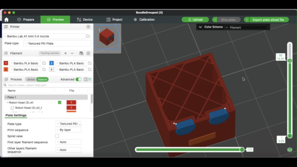
The simple way is to “paint” the STL inside your slicer. But as [CHEP] shows, that is a pain and also has some undesirable side effects. A better approach is to export each part (or, at least, each part of the same color) into separate STL files, which you can then import together in the slicer. You still have to paint, but you don’t have to select different faces, and the resulting coloring is more what you’d expect.
It is easy to write off Tinkercad as a kid’s toy. It is easy enough for kids to learn and it uses bright colors looking more like a video game than a CAD tool. We use a variety of CAD tools, but for something quick, sometimes Tinkercad is just the ticket. Earlier this year, Tinkercad got a sketch feature, something many other CAD programs have and, now, you can even revolve the sketch to form complex objects. Tinkercad guru [HL ModTech] shows you how in the video below.
It wasn’t long ago that we needed to cut an irregular shape out of an STL and we found the sketch feature which was perfect for that purpose. If you’ve used other CAD tools, you’ll know that sketches are typically 2D shapes that get changed into a 3D shape. The traditional thing is to simply extrude it, so if you draw a circle in 2D, you get a cylinder.
If you think about it, STL files are like PDF files. You usually create them using some other program, export them, and then expect them to print. But you rarely do serious editing on a PDF or an STL. But what if you don’t have anything but the STL? [The Savvy Engineer] has a method to help you if you need to reverse engineer an STL file in FreeCAD. Check it out in the video below.
The problem is, of course, that STLs are made up of numerous little triangles. The trick is to switch workbenches and create a shape from mesh. That gets you part of the way.
Once you have a shape, you can convert it to a solid. At that point, you can create a refined copy. This gives you a proper CAD file that you can export to a STEP file. From there, you can use it in FreeCAD or nearly any other CAD package you like to use.
Once you have a proper object, you can easily use it like any other solid body in your CAD program. This is one of those things you won’t need every day, but when you do need it, it’ll come in handy.
Want to up your FreeCAD game? We can help. There are other ways to hack up STL files. You can even import them into TinkerCAD to do simple things, but they still aren’t proper objects.
We don’t know about you, but one of the biggest hassles of having a 3D printer at home or in the ‘shop is the space it takes up. Wouldn’t it be useful if you could fold it down? Well, you’re in luck because over on Hackaday.io, that’s precisely what [Malte Schrader] has achieved with their Portable CoreXY 3D printer.
The typical CoreXY design you find in the wild features a moving bed that starts at the top and moves downwards away from the XY gantry as the print progresses. The CoreXY kinematics take care of positioning the hotend in the XY plane with a pair of motors and some cunning pulley drives. Go check this out if you want to read more about that. Anyway, in this case, the bed is fixed to the base with a 3-point kinematic mount (to allow the hot end to be trammed) but is otherwise vertically immobile. That bed is AC-heated, allowing for a much smaller power supply to be fitted and reducing the annoying cooling fan noise that’s all too common with high-power bed heaters.
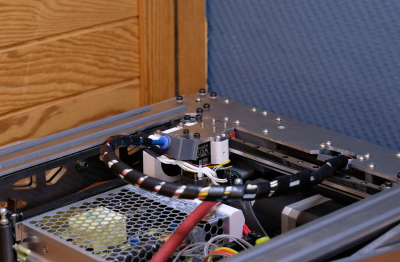
Both ends of the cable bundle are pivoted so it can fold flat inside the frame!
The XY gantry is mounted at each end on a pair of scissor lift mechanisms, which are belt-driven and geared together from a single stepper motor paired with a reduction gearbox. This hopefully will resolve any issues with X-axis tilting that [Malte] reports from a previous version.
The coarse tramming is handled by the bed mounts, with a hotend-mounted BLTouch further dialling it in and compensating for any bed distortion measured immediately before printing. Simple and effective.
As will be clear from the video below, the folding for storage is a natural consequence of the Z-axis mechanism, which we reckon is pretty elegant and well executed—check out those custom CNC machine Aluminium parts! When the Z-axis is folded flat for storage, the hotend part of the Bowden tube feed is mounted to a pivot, allowing it to fold down as well. They even added a pivot to the other end of the cable bundle / Bowden feed so the whole bundle folds down neatly inside the frame. Nice job!
If you want a little more detail about CoreXY kinematics, check out our handy guide. But what about the H-Bot we hear you ask? Fear not, we’re on it.
There are some times when a picture, or better yet a video, really is worth a thousand words, and [heinz]’s dual-disk polar 3D printer is one of those projects. Perhaps the best way to describe it is as an inverted SCARA system that moves the print bed around the hot end, producing strange and mesmerizing motion paths.
The Z-axis runs on a column through the center of the printer, while the print bed is a geared disk that can independently rotate both around its own center and around the central column. This gives the printer a simple way to use multiple extruders: simply mount the extruders at different angles around the central pillar, then rotate the bed around to whichever extruder is currently in use. (See the video demo below.) Since the extruder only moves in the Z direction, there’s also no need to make it as light as possible. In one test, it worked perfectly well with a five-filament direct-drive extruder assembly weighing two kilograms, though it proved a bit unwieldy.
[heinz] 3D printed the rotating disks and a few other parts of the printer, and used two GT2 timing pulleys and the bearings from a Lazy Susan to drive the disks and let them rotate. The print bed’s surface is made out of fiberglass, and since it’s unheated, it has a pattern of small holes drilled into it to let molten plastic seep in and adhere. One nice side effect of the rotating print bed is that it can produce a turntable effect on time-lapse videos.
We’ve covered this project once before when it was a bit earlier in development, and somehow we missed when it got upgraded to its current status. Let’s just say we’re impressed!
I modified a printer a few years ago to handle multiple filaments, but I will admit it was more or less a stunt. It worked, but it felt like you had to draw mystic symbols on the floor of the lab and dance around the printer, chanting incantations for it to go right. But I recently broke down and bought a color printer. No, probably not the one you think, but one that is pretty similar to the other color machines out there.
Of course, it is easy to grab ready-made models in various colors. It is also easy enough to go into a slicer and “paint” colors, but that’s not always desirable. In particular, I like to design in OpenSCAD, and adding a manual intervention step into an otherwise automatic compile process is inconvenient.
The other approach is to create a separate STL file for each filament color you will print with. Obviously, if your printer can only print four colors, then you will have four or fewer STLs. You import them, assign each one a color, and then, if you like, you can save the whole project as a 3MF or other file that knows how to handle the colors. That process is quick and painless, so the question now becomes how to get OpenSCAD to put out multiple STLs, one for each color.
But… color()
OpenSCAD has a color function, but that just shows you colors on the screen, and doesn’t actually do anything to your printed models. You can fill your screen with color, but the STL file you export will be the same. OpenSCAD is also parametric, so it isn’t that hard to just generate several OpenSCAD files for each part of the assembly. But you do have to make sure everything is referenced to the same origin, which can be tricky.
OpenSCAD Development Version Test
It turns out, the development version of OpenSCAD has experimental support for exporting 3MF files, which would allow me to sidestep the four STLs entirely. However, to make it work, you not only have to run the development version, but you also have to enable lazy unions in the preferences. You might try it, but you might also want to wait until the feature is more stable.
Besides, even with the development version, at least as I tried it, every object in the design will still need its color set in the slicer. The OpenSCAD export makes them separate objects, but doesn’t seem to communicate their color in a way that the slicer expects it. If you have a large number of multi-color parts, that will be a problem. It appears that if you do go this way, you might consider only setting the color on the very top-most objects unless things change as the feature gets more robust.
A Better Way
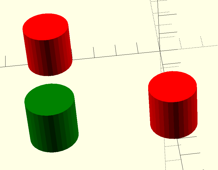
What I really wanted to do is create one OpenSCAD file that shows the colors I am using on the screen. Then, when I’m ready to generate STL files, I should be able to just pick one color for each color I am using.
[Vik Olliver] has been extending the lower resolution limits of 3D printers with the RepRapMicron project, which aims to print structures with a feature size of ten micrometers. A molten plastic extruder would be impractical at such small scales, even if a hobbyist could manufacture one small enough, so instead [Vik]’s working on a system that uses a very fine needle point to place tiny droplets of UV resin on a substrate. These points have to be sharper than anything readily available, so his latest experiments have focused on electrochemically etching his own needles.
The needles start with a fine wire, which a 3D-printed bracket holds hanging down into a beaker of electrolyte, where another electrode is located. By applying a few volts across the circuit, with the wire acting as an anode, electrochemical erosion eventually wears through the wire and it drops off, leaving an atomically sharp point. Titanium wire performs best, but Nichrome and stainless steel also work. Copper wire doesn’t work, and by extension, nor does the plated copper wire sometimes sold as “stainless steel” by sketchy online merchants.
The electrolyte was made from either a 5% sodium chloride solution or 1% nitric acid. The salt solution produced a very thin, fine point, but also produced a cloudy suspension of metal hydroxides around the wire, which made it hard to tell when the wire had broken off. The goal of nitric acid was to prevent hydroxide formation; it produced a shorter, blunter tip with a pitted shaft, but it simply etched the tip of the wire to a point, with the rest of the wire never dropping off. Some experimentation revealed that a mixture of the two electrolyte solutions struck a good balance which etched fine points like the pure salt solution, but also avoided cloudy precipitates.
If you’re interested in seeing more of the RepRapMicron, we’ve looked at a previous iteration which scribed a minuscule Jolly Wrencher in marker ink. On a more macro scale, we’ve also seen one 3D printer which used a similar resin deposition scheme.