That’s a lot of qualifications, but we’re pretty sure that you can’t accuse us of hyperbole in the title: this is one of the tightest little 3D printer builds we’ve ever seen. Add in the slightly esoteric CoreXY kinematics and the thick aluminum frame, and it’s a speed demon in addition to being a looker.
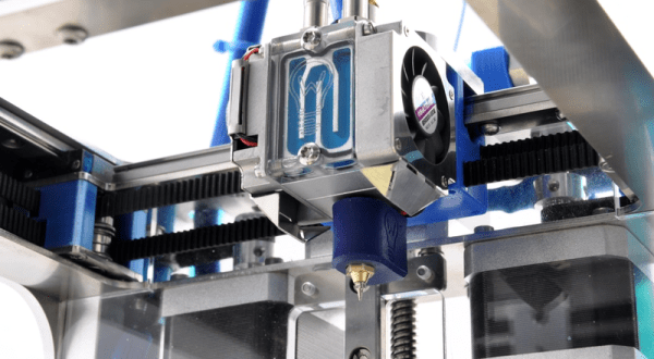
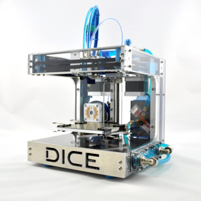 [René] had built a few 3D printers before, so he had a good feel for the parameters and design tradeoffs before he embarked on the DICE project. Making a small print volume, for instance, means that the frame can be smaller and thus exponentially more rigid. This means that it’s capable of very fast movements — 833 mm/s is no joke! It also looks to make very precise little prints. What could make it even more awesome? Water-cooled stepper motors, magnetic interchangeable printheads, and in-built lighting.
The build looks amazing, and there is video documentation of the whole thing on [René]’s site, including a full bill of materials and designs. It’s certainly not the cheapest 3D printer we’ve ever seen, and the tiny build platform makes it a bad choice for a general-purpose machine, but if you need a second printer and you want one with style, the DICE looks hard to beat.
Thanks [Laimonus Mockus] for the tip!