This excellent content from the Hackaday writing crew highlights recurring topics and popular series like Linux-Fu, 3D-Printering, Hackaday Links, This Week in Security, Inputs of Interest, Profiles in Science, Retrotechtacular, Ask Hackaday, Teardowns, Reviews, and many more.
The chat functionality on Hackaday.io is quickly turning into the nexus of all things awesome. This Tuesday, February 28th, everyone’s favorite robotic dog is talking certifications. Everything from FCC to UL to OSH to CE and the other CE is on the table. If you want to build hardware, and especially if you want to build a product, this is the talk for you. Join us for the next Tindie Chat on Hackaday.io.
Every month or so, we round up Tindie sellers, buyers, and the Tindie curious to talk about the issues facing hardware creators. We meet up in the Tindie Dog Park to talk about all things Tindie and hardware creation. If you want to know anything about certifications — whether you’re selling on Tindie or not — this is the virtual meetup for you.
This chat is going down Tuesday, February 28th at 11:00 AM PST (or 19:00 GMT). Want to join in the chat? Head on over to the Tindie Dog Park and request to join the project. Then, just head over to the chat by clicking on the ‘Team Messaging’ button. If you have a question, we have a spreadsheet.
There are a lot of experienced product designers over on Tindie, and this is a prime opportunity to learn some of the hard lessons these Tindie sellers have already experienced. Don’t miss this, it’s going to be great.
There is an old saying: “In theory, theory and practice are the same. In practice, they are not.” We spend our time drawing on paper or a computer screen, perfect wires, ideal resistors, and flawless waveforms. Alas, the real world is not so kind. Components have all kinds of nasty parasitic effects and no signal looks like it does in the pages of a text book.
Consider the following problem. You have a sine wave input coming in that varies between 0 V and 5 V. You want to convert it to a square wave that is high when the sine wave is over 2.5 V. Simple, right? You could use a CMOS logic gate or a comparator. In theory…
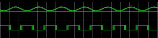
The problem is, the sine wave isn’t perfect. And the other components will have little issues. If you’ve ever tried this in real life, you’ll find that when the sine wave is right at the 2.5 V mark the output will probably swing back and forth before it settles down. This is exacerbated by any noise or stretching in the sine wave. You will wind up with something like this:
Notice how the edges of the square wave are a bit fat? That’s the output switching rapidly back and forth right at the comparator’s threshold.
Hysteresis
The answer is to not set the threshold at 2.5 V, or any other single value. Instead, impose a range outside of which it will switch, switching low when it leaves the low end of the range, and high when it exceeds the high end. That is, you want to introduce hysteresis. For example, if the 0 to 1 shift occurs at, say, 1.9 V and the 1 to 0 switch is at 0.5 V, you’ll get a clean signal because once a 0 to 1 transition happens at 1.9 V, it’ll take a lot of noise to flip it all the way back below 0.5 V.
You see the same effect in temperature controllers, for example. If you have a heater and a thermal probe, you can’t easily set a 100 degree set point by turning the heater off right away when you reach 100 and then back on again at 99.9999. You will usually use hysteresis in this case, too (if not something more sophisticated like a PID). You might turn the heater off at 99 degrees and back on again at 95 degrees, for example. Indeed, your thermostat at home is a prime example of a system with hysteresis — it has a dead-band of a few degrees so that it’s not constantly turning itself on and off.
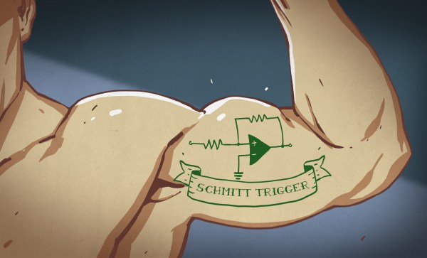
Schmitt Triggers and How to Get One
A Schmitt Trigger is basically a comparator with hysteresis. Instead of comparing the incoming voltage with VCC / 2, as a simple comparator would, it incorporates a dead band to ensure that logic-level transitions occur only once even in the presence of a noisy input signal.
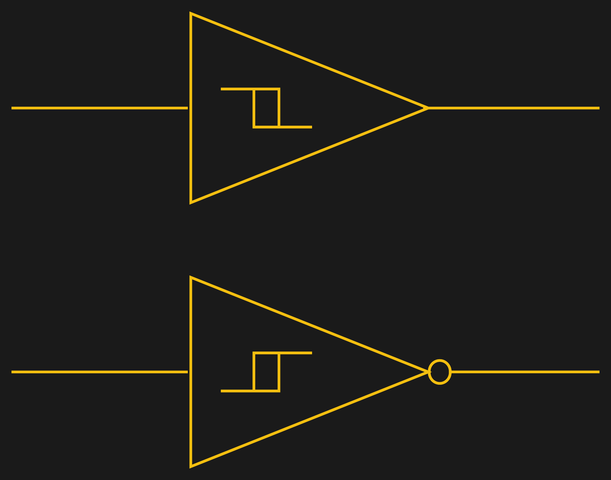
Assuming you want a Schmitt trigger in a circuit, you have plenty of options. There are ICs like the 74HC14 that include six (inverting) Schmitt triggers. On a schematic, each gate is represented by one of the symbols to the right; the little mark in the box is the hysteresis curve, and the little bubble on the output indicates logical negation when it’s an inverter.
You can also make them yourself out of transistors or even a 555 chip. But the easiest way by far is to introduce some feedback into a plain op amp comparator circuit.
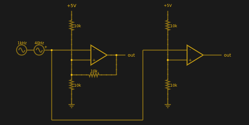
Below are two op amps, one with some positive feedback to make it act like a Schmitt trigger. The other is just a plain comparator. You can simulate the design online.
If you haven’t analyzed many op amp circuits, this is a good one to try. First, imagine an op amp has the following characteristics:
The inputs are totally open.
The output will do whatever it takes to make the inputs voltages the same, up to the power supply rails.
Neither of these are totally true (theory vs. practice, again), but they are close enough.
The comparator on the right doesn’t load the inputs at all, because the input pins are open circuit, and the output swings to either 0 V or 5 V to try, unsuccessfully, to make the inputs match. It can’t change the inputs because there is no feedback, but it does make a fine comparator. The voltage divider on the + pin provides a reference voltage. Anything under that voltage will swing the output one way. Over the voltage will swing it the other way. If the voltages are exactly the same? That’s one reason you need hysteresis.
The comparator’s voltage divider sets the + pin to 1/2 the supply voltage (2.5 V). Look at the Schmitt trigger (on top). If the output goes between 0 V and 5 V, then the voltage divider winds up with either the top or bottom resistor in parallel with the 10K feedback resistor. That is, the feedback resistor will either be connected to 5 V or ground.
Of course, two 10K resistors in parallel will effectively be 5K. So the voltage divider will be either 5000/15000 (1/3) or 10000/15000 (2/3) depending on the state of the output. Given the 5 V input to the divider, the threshold will be 5/3 V (1.67 V) or 10/3 V (3.33 V). You can, of course, alter the thresholds by changing the resistor values appropriately.
Practical Applications
Schmitt triggers are used in many applications where a noisy signal requires squaring up. Noisy sensors, like an IR sensor for example, can benefit from a Schmitt trigger. In addition, the defined output for all voltage ranges makes it handy when you are trying to “read” a capacitor being charged and discharged. You can use that principle to make a Schmitt trigger into an oscillator or use it to debounce switches.
If you want to see a practical project that uses a 555-based Schmitt, check out this light sensor. The Schmitt trigger is just one tool used to fight the imprecision of the real world and real components. Indeed, they’re nearly essential any time you want to directly convert an analog signal into a one-bit, on-off digital representation.
Hackaday and Tindie will be at SCALE Friday through Sunday, showing off the coolest parts of Hackaday, Hackaday.io, and our lovable robotic dog, Tindie. We’ll be handing out t-shirts and stickers, and we’ll be giving tours of the SupplyFrame Design Lab located just two blocks away from the convention center. The Design Lab is a crown jewel of our corporate overlord’s emphasis on Open Hardware, and if you want to see where the magic happens, this is your chance. We’ll be running tours of the Lab on Friday, so find the Hackaday and Tindie crew in the expo area around 3:40 PM.
I’ve been soldering for a long time, and I take pride in my abilities. I won’t say that I’m the best solder-slinger around, but I’m pretty good at this essential shop skill — at least for through-hole and “traditional” soldering; I haven’t had much practice at SMD stuff yet. I’m confident that I could make a good, strong, stable joint that’s both electrically and mechanically sound in just about any kind of wire or conductor.
But like some many of us, I learned soldering as a practical skill; put solder and iron together, observe results, repeat the stuff that works and avoid the stuff that doesn’t. Seems like adding a little inside information might help me improve my skills, so I set about learning what’s going on mechanically and chemically inside a solder joint.
When my elder brother and I were kids back in the late 1970’s, our hacker Dad showed us this 1960-61 catalog of the Atlas Lighting Co (later Thorn Lighting) with an interesting graphic design on the cover. He told us to do a thought experiment, asking us to figure out how it would be possible to have a machine that would draw the design on that catalog cover.
Incorrectly, our first thought was that the design was created with a Spirograph. A spirograph has two main parts: a large ring with gear teeth on the inside and outside circumferences and a set of smaller, toothed wheels with holes in them for inserting a drawing instrument — usually a ball point pen. You hold the big ring, insert the pen in the smaller wheel, and then mesh and rotate the smaller wheel around the big ring. But spirographs can’t be used to draw irregular, asymmetrical figures. You could always recreate a design. Because of the nature of gears, none of them were unique, one off, designs.
A spirograph set like this cannot make the image above [Image credit: Multicherry CC-BY-SA 3.0]We figured adding some lever arms, and additional geared wheels (compound gears) could achieve the desired result. It turns out that such a machine is called a Cycloid Drawing Machine. But even with this kind of machine, it was possible to replicate a design as often as required. You would fix the gears and levers and draw a design. If the settings are not disturbed, you can make another copy. Here’s a video of a motorized version of the cycloid machine.
The eventual answer for making such designs was to use a contraption called as the harmonograph. The harmonograph is unique in the sense that while you can make similar looking designs, it would be practically impossible to exactly replicate them — no two will be exactly the same. This thought experiment eventually led to my brother building his own harmonograph. This was way back when the only internet we had was the Library, which was all the way across town and not convenient to pop in on a whim and fancy. This limited our access to information about the device, but eventually, after a couple of months, the project was complete.
Over the last few weeks, our weekly Hack Chats on hackaday.io have gathered a crowd. This week, we’re talking about the greatest threat humanity has ever faced: toasters with web browsers.
The topic of this week’s Hack Chat is Security for IoT, because someone shut down the Internet with improperly configured webcams.
This chat is hosted by the Big Crypto Team at the University of Pittsburgh. [Wenchen Wang], [Ziyue Sun], [Brandon Contino], and [Nick Albanese] will be taking questions about lightweight devices connected to the Internet. Discussion will include building things that connect to larger networks securely.
The Big Crypto team at UP are thinking about the roadblocks people have to implement security in their projects, and if apathy or ignorance is the main reason security isn’t even considered in the worst IoT offenders.
The Hack Chat is scheduled for Friday, February 24th at noon PST (20:00 GMT).
Here’s How To Take Part:
Our Hack Chats are live community events on the Hackaday.io Hack Chat group messaging.
Log into Hackaday.io, visit that page, and look for the ‘Join this Project’ Button. Once you’re part of the project, the button will change to ‘Team Messaging’, which takes you directly to the Hack Chat.
You don’t have to wait until Friday; join whenever you want and you can see what the community is talking about.
Upcoming Hack Chats
These Hack Chats are becoming very popular, and that’s due in no small part to the excellent lineup of speakers we’ve hosted. Already, we’ve had [Lady Ada], [Sprite_tm], and [bunnie] — engineers, hackers, and developers who are at the apex of their field. We’re not resting on our laurels, though: in a few weeks we’ll be hosting Hack Chats with [Roger Thornton], an engineer with Raspberry Pi, and Fictiv, masters of mechanical manufacturing.
3D printers are the single best example of what Open Hardware can be. They’re useful for prototyping, building jigs for other tools, and Lulzbot has proven desktop 3D printers can be used in industrial production. We endorse 3D printing as a viable tool as a matter of course around here, but that doesn’t mean we think every house should have a 3D printer.
Back when Bre was on Colbert and manufacturing was the next thing to be ‘disrupted’, the value proposition of 3D printing was this: everyone would want a 3D printer at home because you could print plastic trinkets. Look, a low-poly Bulbasaur. I made a T-rex skull. The front page of /r/3Dprinting. Needless to say, the average consumer doesn’t need to spend hundreds of dollars to make their own plastic baubles when WalMart and Target exist.
The value proposition of a 3D printer is an open question, but now there is some evidence a 3D printer provides a return on its investment. In a paper published this week, [Joshua Pearce] and an undergraduate at Michigan Tech found a 3D printer pays for itself within six months and can see an almost 1,000% return on investment within five years. Read on as I investigate this dubious claim.





![A spirograph set like this cannot make the image above[Image credit: Multicherry CC-BY-SA 3.0]](https://hackaday.com/wp-content/uploads/2017/02/spirograph_set_uk_palitoy_early_1980s_perspective_fixed.jpg)