Underwater Logging For Science

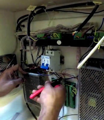
Logging data with an Arduino is old-hat for most Hackaday readers. However, [Patricia Beddows] and [Edward Mallon] had some pretty daunting requirements. Their sensors were going underground and underwater as part of an effort to study conditions underwater and in caves. They needed to be accessible, yet rugged. They didn’t want to use batteries that would be difficult to take on airplanes, but also wanted more than a year of run time. You can buy all that, of course, if you are willing to pay the price.

Instead, they used off-the-shelf Arduino boards connected together inside PVC housings. Three alkaline AA batteries are compact and give them more than a year of run time. They wrote a journal paper to help other scientists use the same techniques for the Sensors journal published by the Multidisciplinary Digital Publishing Institute.

Continue reading “Underwater Logging For Science”

Building An Arduino Smart IC Tester For $25

There’s no question that you can get a lot done with the classic multimeter; it’s arguably the single most capable tool on your bench. But the farther down the rabbit hole of hacking and reverse engineering you go, the more extravagant your testing and diagnostic gear tends to get. For some of us that’s just an annoying reality of the game. For others it’s an excuse to buy, and maybe even build, some highly specialized equipment. We’ll give you one guess as to which group we fall into here at Hackaday.

[Akshay Baweja] is clearly a member of the second group. He’s recently published a guide on building a very slick intelligent Integrated Circuit tester with a total cost of under $25 USD. Whether you’re trying to identify an unknown chip or verifying your latest parts off the slow-boat from China actually work before installing them in your finished product, this $25 tool could end up saving you a lot of time and aggravation.

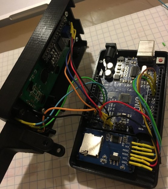
[Akshay] walks readers through the components and assembly of his IC tester, which takes the form of a Shield for the Arduino Mega 2560. The custom PCB he designed and had manufactured holds the 20 Pin ZIF Socket as well as the 2.4 inch TFT touch screen. The screen features an integrated micro SD slot which is important as you need the SD card to hold the chip database.

With an IC to test inserted into the ZIF socket, the user can have the tester attempt to automatically ID the chip or can manually enter in a part number to lookup. The source code for the Arduino as well as the chip ID database is up on GitHub for anyone looking to add some more hardware to the device’s testing repertoire.

The importance of good test equipment simply cannot be overstated. Between highly specialized gear like this IC tester to classic instruments such as the oscilloscope, your bench is going to be full of weird and wonderful pieces of equipment before too long.

Continue reading “Building An Arduino Smart IC Tester For $25”

Arduino Keyboard Is Gorgeous Inside And Out

While the vast majority of us are content to plod along with the squishy chiclet keyboards on our laptops, or the cheapest USB membrane keyboard we could find on Amazon, there’s a special breed out there who demand something more. To them, nothing beats a good old-fashioned mechanical keyboard, where each key-press sounds like a footfall of Zeus himself. They are truly the “Chad” of the input device world.

But what if even the most high end of mechanical keyboards doesn’t quench your thirst for spring-loaded perfection? In that case, the only thing left to do is design and build your own. [Matthew Cordier] recently unveiled the custom mechanical keyboard he’s been working on, and to say it’s an elegant piece of engineering is something of an understatement. It may even look better inside than it does on the outside.

The keyboard, which he is calling z.48, is based around the Arduino Pro Micro running a firmware generated on kbfirmware.com, and features some absolutely fantastic hand-wiring. No PCBs here, just a rainbow assortment of wire and the patience of a Buddhist monk. The particularly attentive reader may notice that [Matthew] used his soldering iron to melt away the insulation on his wires where they meet up with the keys, giving the final wiring job a very clean look.

Speaking of the keys, they are Gateron switches with DSA Hana caps. If none of those words mean anything to you, don’t worry. We’re through the Looking Glass and into the world of the keyboard aficionado now.

Finally, the case itself is printed on a CR-10 with a 0.3 mm nozzle and 0.2 mm layers giving it a very fine finish. At 70% infill, we imagine it’s got a good deal of heft as well. [Matthew] mentions that a production case and a PCB are in the cards for the future as he hopes to do a small commercial run of these boards. In the meantime we can all bask in the glory of what passes for a prototype in his world.

We’ve seen some exceptionally impressive mechanical keyboards over the years, including the occasional oddity like the fully 3D printed one and even one that inexplicably moves around. But this build by [Matthew] has to be one of the most elegant we’ve ever come across.

Your Audio Will Be Back, Right After This Commercial Break

[LittleTern] — annoyed by repetitive advertisements — wanted the ability to mute their Satellite Box for the duration of every commercial break. Attempts to crack their Satellite Box’s IR protocol went nowhere, so they thought — why not simply mute the TV?

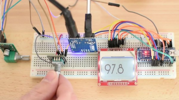
Briefly toying with the idea of a separate remote for the function, [LittleTern] discarded that option as quickly as one tends to lose an additional remote. Instead, they’re using the spare RGYB buttons on their Sony Bravia remote — cutting down on total remotes while still controlling the IR muting system. Each of the four coloured buttons normally don’t do much, so they’re set do different mute length timers — customized for the channel or time of day. The system that sends the code to the TV is an Arduino Pro Mini controlling an IR LED and receiver, with a status LED set to glow according to which button was pressed.

Continue reading “Your Audio Will Be Back, Right After This Commercial Break”

Designing a mini spy bug recorder

Mini Spy Bug Walkthrough

What we like most about [GreatScott’s] project videos is that he not only shows making them but also the calculations for selecting parts and the modifications along the way. This time he’s made a mini spy bug that records up to nine hours of audio.

His first task was to figure out if the ATmega328p’s ADC is suitable for audio sampling, but only after he explains how sampling works by periodically checking the input voltage from the microphone. Checking the datasheet he found that the ADC’s fastest conversion time is 13 microseconds, which works out to a sampling rate of 76.923 kHz. Good enough.

He then walks through why and how he decided to go with a pre-made amplifier circuit built around the MAX9814 IC. Spoiler alert. His electret’s amplifier output voltage was too low, using an off-the-shelf circuit instead of making his own kept things simple, and the circuit has automatic gain control.

At this point, he added the MicroSD card adapter. Why not just transmit the audio over FM as so many others have done with their hacks? Perhaps he’s worried about someone detecting the transmission and finding his bug.

His final optimization involved getting a good battery life. He measured the circuit’s current draw at 20 milliamps. With a 160 mAh battery capacity, that would be 8 hours of recording time. Removing the Arduino Pro Mini’s voltage regulator and two LEDs got the current down to 18 milliamps and a recording time of 9 hours. Better.

Those are the highlights. Enjoy his full walkthrough in the video below.

Continue reading “Mini Spy Bug Walkthrough”

Debugging An Arduino With An Arduino

As every Hackaday reader knows, and tells us at every opportunity in the comments, adding an Arduino to your project instantly makes it twice as cool. But what if, in the course of adding an Arduino to your project, you run into a problem and need to debug the code? What if you could use a second Arduino to debug the first? That would bring your project up to two Arduinos, instantly making it four times as awesome as before you started! Who could say no to such exponential gains?

Debugging an ATTiny85

Not [Wayne Holder], that’s for sure. He writes in to let us know about a project he’s been working on for a while that allows you to debug the execution of code on an Arduino with a second Arduino. In fact, the target chip could even be another AVR series microcontroller such as a the ATTiny85. With his software you can single-step through the code, view and modify values in memory, set breakpoints, and even disassemble the code. Not everything is working fully yet, but what he has so far is very impressive.

The trick is exploiting a feature known as “debugWIRE” that’s included in many AVR microcontrollers. Unfortunately documentation on this feature is hard to come by, but with some work [Wayne] has managed to figure out how most of it works and create an Arduino Sketch that lets the user interact with the target chip using a simple menu system over the serial monitor, similar to the Bus Pirate.

[Wayne] goes into plenty of detail on his site and in the video included after the break, showing many of the functions he’s got working so far in his software against an ATTiny85. If you spend a lot of time working on AVR projects, this looks like something you might want to keep installed on an Arduino in your tool bag for the future.

Debugging microcontroller projects can be a huge time saver when your code starts running on real hardware, but often takes some hacking to get working.

Continue reading “Debugging An Arduino With An Arduino”

I’ll Have A Beer With A Compliment Chaser

[Andrew MacPherson] found out that compliments, even insincere ones, make the recipients feel better. So, he put together a thermal printer and a hilariously large button with an Arduino and created a machine that prints compliments. And where best to put a machine that prints out compliments? The local bar, where else?

An Arduino Nano clone runs the show connected to a thermal printer. The Nano clone didn’t like the 9 volt power supply, so a buck converter was used to reduce the voltage down to 5 volts for the Nano, while the printer gets the full power. During initial trials, the printer was very slow to print and it took [Andrew] a while to adjust the parameters – after tweaking the speed as well as the heating time, he was able to get the printer working without burning the paper or taking forever to print.

Once the machine was working, it was time to add a button. A large, light-up button was connected and glued to the side of the printer. More glue was used (after some “modifications” to the printer chassis) to secure a barrel connector for the power adapter.

[Andrew] decided that since he’s down at his favorite bar quite a lot, he’d set it up there. The customers could push the button and receive a compliment while drowning their sorrows. He got a friend of his who’s a copywriter to come up with some nicely written compliments to print out. The printer was such a hit that the bartender sent [Andrew] a message on Facebook saying so. If you have a thermal printer lying around, you can use this tutorial to connect it to the internet, or, if you don’t have one, you can build your own.

Continue reading “I’ll Have A Beer With A Compliment Chaser”