Hardware projects often fall into three categories: Those that flash lights, those that make sounds and those that move. This virtuoso performance by [Kevin]’s “Lo-Fi Orchestra” manages all three, whilst doing an excellent job of reproducing the 1973 musical classic Tubular Bells by Mike Oldfield.
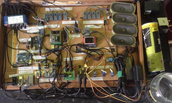
Producing decent polyphonic sounds of different timbres simultaneously is a challenge for simple microcontroller boards like Arduinos, so [Kevin] has embraced the “More is more” philosophy and split up the job of sound generation in much the same way as a traditional orchestra might. Altogether, 11 Arduino Nanos, 6 Arduino Unos, an Arduino Pro Mini, an Adafruit Feather 32u4, and a Raspberry Pi running MT32-Pi make up this electronic ensemble.
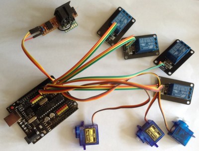
The servo & relay drumkit is a particular highlight, providing some physical sounds to go along with the otherwise solid-state generation.
The whole project is “conducted” over MIDI and the flashing sequencer in the middle gives a visual indication of the music that is almost hypnotic. The performance is split into two videos (after the break), and will be familiar to fans of 70’s music and classic horror movies alike. We’re astonished how accurately [Kevin] has captured the mood of the original recording.
If this all looks slightly familiar, it may be because we have covered the Lo-Fi Orchestra before, when it entertained us with a rousing rendition of Gustav Holst’s Planets Suite. If you’re more interested in real Tubular Bells than synthesized ones, then check out this MIDI-controlled set from 2013. Continue reading “Lo-Fi Orchestra Learns Tubular Bells“