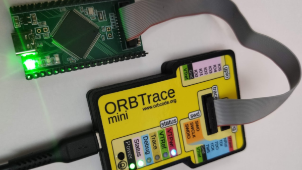
Linux Fu: The Infinite Serial Port

Ok, the title is a bit misleading. Like most things in life, it really isn’t infinite. But I’m going to show you how you can use a very interesting Linux feature to turn one serial port from a microcontroller into a bunch of virtual ports. In theory, you could create over 200 ports, but the reality is you will probably want to stick with fewer.

The feature in question is what’s known as pseudoterminal or sometimes a pty or pts. These special files were made to feed data to programs that expect to accept data from a terminal. The files provide two faces. To the client, it looks like any other terminal device. To the creator, though, it is just another file. What you write to that file goes to the fake terminal and you can read anything that is sent from the program connected to the terminal. You use these all the time, probably, without realizing it since running a shell under X Windows, for example, doesn’t attach to a real terminal, after all.

You could, of course, do the same trick with a composite USB device, assuming you have one. Also assuming you can find a working driver and get it working. However, many microcontrollers have a serial port — even one with a USB converter built-in — but fewer have full-blown USB hardware. Even the ones that do are often at odds with strange drivers on the PC side. Serial ports work and work well even on the simplest microcontrollers.

The Plan

The plan is simple enough. A Linux program listens to a real serial port and watches for special character sequences in the data stream. Those sequences will allow you to switch data so that the data stream will go to a particular terminal. Data coming back from the terminals will go to the real serial port after sending a sequence that identifies its source.

Continue reading “Linux Fu: The Infinite Serial Port”

A Rotary Encoder: How Hard Can It Be?

As you may have noticed, I’ve been working with an STM32 ARM CPU using Mbed. There was a time when Mbed was pretty simple, but a lot has changed since it has morphed into Mbed OS. Unfortunately, that means that a lot of libraries and examples you can find don’t work with the newer system.

I needed a rotary encoder — I pulled a cheap one out of one of those “49 boards for Arduino” kits you see around. Not the finest encoder in the land, I’m sure, but it should do the job. Unfortunately, Mbed OS doesn’t have a driver for an encoder and the first few third-party libraries I found either worked via polling or wouldn’t compile with the latest Mbed. Of course, reading an encoder isn’t a mysterious process. How hard can it be to write the code yourself? How hard, indeed. I thought I’d share my code and the process of how I got there.

There are many ways you can read a rotary encoder. Some are probably better than my method. Also, these cheap mechanical encoders are terrible. If you were trying to do precision work, you should probably be looking at a different technology like an optical encoder. I mention this because it is nearly impossible to read one of these flawlessly.

So my goal was simple: I wanted something interrupt driven. Most of what I found required you to periodically call some function or set up a timer interrupt. Then they built a state machine to track the encoder. That’s fine, but it means you eat up a lot of processor just to check in on the encoder even if it isn’t moving. The STM32 CPU can easily interrupt with a pin changes, so that’s what I wanted.

The Catch

The problem is, of course, that mechanical switches bounce. So you have to filter that bounce either in hardware or software. I really didn’t want to put in any extra hardware more than a capacitor, so the software would have to handle it.

I also didn’t want to use any more interrupts than absolutely necessary. The Mbed system makes it easy to handle interrupts, but there is a bit of latency. Actually, after it was all over, I measured the latency and it isn’t that bad — I’ll talk about that a little later. Regardless, I had decided to try to use only a pair of interrupts.

Continue reading “A Rotary Encoder: How Hard Can It Be?”

Arm Pumps Up The Volume With Mbed And A Potentiometer

Last time, I told you how to get started with the “Black Pill” STM32F411 board using the Mbed OS. The example program, admittedly, didn’t use many of the features of the OS, unless you count what the USB serial port driver uses behind the scenes. However, this time, we’ll make a practical toy that lets you adjust your PC’s volume level with a pot.

The Black Pill module on a breadboard.

The Black Pill is a good choice for this application since it has analog inputs and can act as a USB keyboard. In fact, the Mbed OS has drivers for all kinds of USB devices. We’ve seen the serial port, but you can also look like a mass storage device or a mouse, for example. Just for practice, we’ll create two threads of execution. One will read the pot and send a message over to the other thread. That thread will communicate with the PC as a USB keyboard. Any computer that understands media keys on a keyboard should work with the device.

Threads

Creating threads is very simple. For many cases, you just define a void function that takes no arguments and use it with a Thread object:

readknobThread.start(vol_thread);

Of course, the function shouldn’t return unless you want the thread to end. As I mentioned in the last post, you can sleep with the ThisThread::sleep_for call. There is also a yield call if you simply want to give up the time slice without sleeping for a specific amount of time.

Continue reading “Arm Pumps Up The Volume With Mbed And A Potentiometer”

Arming With An OS

We see tons of projects with the infamous “Blue Pill” STM32 boards. They are cheap and plentiful and have a lot of great features, or at least they were before the chip shortage. I recently picked up a “Black Pill”, which is very similar but has an even more powerful processor. For a few bucks, you get an ARM CPU that can run at 100 MHz (but with USB, probably 96 MHz). There’s 512 kB of flash and 128 kB of RAM. There’s a USB type C port, and even a button and an LED onboard. The thing fits on a breadboard and you can program it with a cheap STLink dongle which costs about $10.

The Black Pill module on a breadboard.

Of course, you then have to consider the software. The STM32Cube stuff is a lot to set up and learn but it does let you do just about anything you can imagine. Then there is the STM32Duino plug-in that lets you use it as a beefy Arduino. That works and is easy enough to set up. However, there’s also Mbed. The only problem is that Mbed doesn’t work right out of the box. Turns out, though, it isn’t that hard to set up. I’ll show you how easy it is to get things going and, next time, I’ll show you a practical example of a USB peripheral that uses the mBed RTOS features.

First Steps

Obviously, you are going to need a Black Pill. There are at least two choices but for as cheap as they are there is little reason not to get the STM32F411 version that has more memory. The DIP form factor will fit in whatever breadboard you happen to have and a USB C cable will power the board so unless you are driving a lot of external circuitry, you probably don’t need an external supply.

Continue reading “Arming With An OS”

A Power Button For Raspberry Pi, Courtesy Of Device Tree Overlays

As a standard feature of the Linux kernel, device tree overlays (DTOs) allow for easy enabling and configuration of features and drivers, such as those contained within the standard firmware of a Raspberry Pi system. Using these DTOs it’s trivial to set up features like as a soft power-off button, triggering an external power supply and enable drivers for everything from an external real-time clock (RTC) to various displays, sensors and audio devices, all without modifying the operating system or using custom scripts.

It’s also possible to add your own DTOs to create a custom overlay that combines multiple DTO commands into a single one, or create a custom device tree binary (DTB) for the target hardware. Essentially this DTB is loaded by the Linux kernel on boot to let it know which devices are connected and their configuration settings, very similar to what the BIOS component with x86-based architectures handles automatically.

Ultimately, the DTB concept and the use of overlays allow for easy configuration of such optional devices and GPIO pin settings, especially when made configurable through a simple text file as on the Raspberry Pi SBC platform.

Continue reading “A Power Button For Raspberry Pi, Courtesy Of Device Tree Overlays”

An M-Core module plugged into its devboard. Around it are Ethernet, HDMI, Type-C, two USB-A ports, one MicroSD card socket and one unpopulated footprint for a WiFi module

MangoPi To Bring A SD-Card-Sized Linux Module

Today’s Diminutive Device is a small castellated System-On-Module (Twitter link, nitter proxy) from [MangoPi] called M-Core, with a quad-core A53 CPU and 1 GB of RAM. As such, it’s very capable of running Linux, and even sports an HDMI output! Taking a closer look at the devboard picture, we can spot traces for three USB 2.0 ports, what seems to be two SDIO interfaces for MicroSD or WiFi cards, and an Ethernet MagJack with its termination network. This is a decent set of interfaces, rivaling what we’d expect out of a Pi Zero!

More importantly, this module is as small as an SD card itself – or as an OLED display that we hobbyists sprinkle onto our projects. Having power of Linux in such a small footprint is certainly something to behold! The back of the module is mostly flat, save for a few decoupling capacitors on the other side of the CPU – it seems, an Allwinner H616. On top of it, we can see the CPU itself, a small buck regulator and a DDR3 RAM chip, as well as tightly-packed passives. There’s even an unpopulated footprint for a DFN8 QSPI flash chip – with a lightweight enough OS build, you could perhaps dedicate your MicroSD card to storage only.

The devboard for uses the “FlexyPins”-like connectivity technique we’ve covered recently, and [MangoPi] say they bought those pins on TaoBao. We can’t help but be a bit amused at the thought of putting HDMI through such connections, but it seems to work well enough! Castellated modules like these are relatively easy to work with, so it shouldn’t be hard to literally pop this module out of the devboard and figuratively pop it onto your PCB. Next step is, reportedly, porting Armbian to this board, likely solving quite a few software support hurdles.

MangoPi have been posting updates on their Twitter page over the last few weeks, and, as it comes with the format, a lot of questions are left unanswered. Why does the devboard only show a single linear regulator of the kind we typically expect to deliver 1 A at most? Will we get higher-RAM versions? What’s the price going to look like? Will this module ever get to market? We can only hope, but if it does indeed, we are sure to see a few projects with these, whether it’s smart glasses, smart displays, phones, handhelds or malicious wall chargers. As usual, community makes or breaks an SBC, and we shall watch this one closely.

We thank [WifiCable] and [DjBiohazard] for sharing this with us!

The BGA chip in question flipped onto a piecce of breadboard, all its pins broken out with magnet wire.

Heroic Efforts Give Smallest ARM MCU A Breakout, Open Debugger

In today’s episode of Diminutive Device Technology Overview, [Sprite_TM] is at it again – this time conquering the HC32L110. A few weeks ago, we have highlighted the small ARM Cortex M0+ microcontroller, which is outstanding because of its exceptionally small size. We also pointed out a few hurdles, among them – hard-to-approach SDK and documentation, and difficulties making and assembling a PCB for such a small BGA. Today, we witness how [Sprite_TM] bulldozed through all of these hurdles for all of us, and added a few pictures to our collective “outrageous soldering” galleries while at it.

First, he figured out an example layout for this MCU that’s achievable for us even on a cheapest 2-layer board from JLCPCB, keeping distances within the generic tolerance standards by snubbing out a few pins. As a result, we only lose access to four GPIOs – those will have to be kept as inputs, so that nothing burns out. However, that’s the kind of tradeoff we are okay making if it helps us keep our PCB small and lightweight for projects where these factors matter. After receiving the resulting board, he also recorded a short tutorial on soldering such packages at home with a mere hot air gun and a few bare necessities like flux and tweezers – embedded below.

It doesn’t end there, however, as he decided to work around the GPIO fanout limitation in a non-intended way. Evidently, [Sprite_TM] decided to have some fun, taking a piece of regular 0.1″ spacing protoboard and deadbugging the chip with magnet wire, much to our amusement. The resulting contraption, pictured above, worked – and this is ever something you’d like to be able to achieve yourself in times of dire need, whether you make something work or simply to be entertained by making use of a cursed mounting technique, there’s an one-hour-long livestream recording of how this magnet wire contraption came to be. And, of course, that wasn’t the last thing to be shared.

Continue reading “Heroic Efforts Give Smallest ARM MCU A Breakout, Open Debugger”