It might seem almost comical to our more fresh-faced readers, but there was a time when you could go into a big box retailer and purchase what was known as a “DivX Player”. Though they had the outward appearance of a normal DVD player, these gadgets could read various digital video file formats off of a CD-R or DVD-R, complete with rudimentary file browser. Depending on how much video compression you could stomach, a player like this would allow you to pack an entire season of a show or multiple movies onto a single disc. Before we started streaming everything online, that was kind of a big deal.
[Roberto Piva] got his hands on one of these early digital media players, a KiSS DP-500 circa 2003, and decided that it was too unique to send off to the recycling center. Not only was he curious about what made it tick, but he thought it would be interesting to try converting it into a Raspberry Pi powered streaming media player. One might say there’s something almost perverse about taking the carcass of one of these devices and stuffing it full of the same technology that made it obsolete in the first place, but who are we to judge?
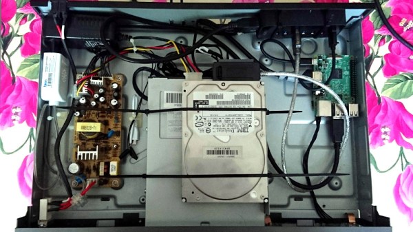
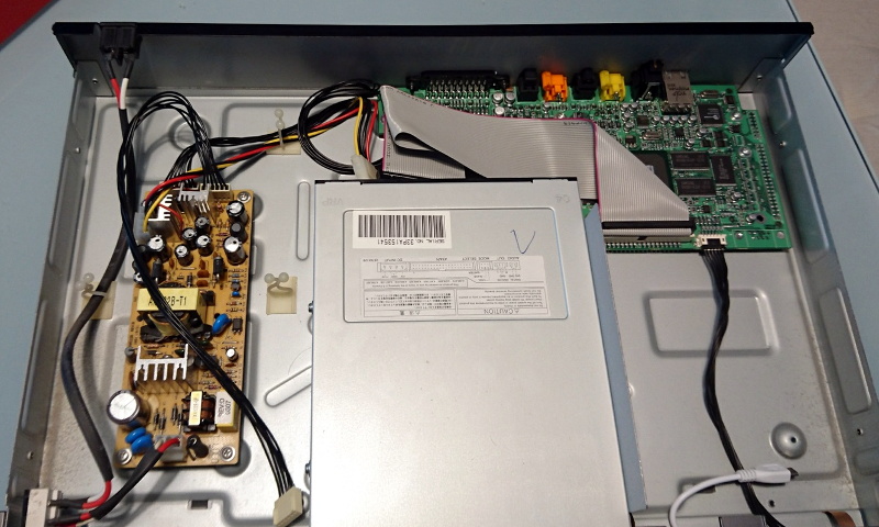
Upon opening the vintage set top box, [Roberto] was immediately struck by how empty the thing was. He got the impression the device was a rush job, pushed out to capitalize on a relatively short-lived trend. Looking at it, we have to agree. It’s almost as though they got a deal on some old VCR chassis laying around in a warehouse someplace and decided to stick some (at the time) modern electronics in it. It even uses what appears to be a standard IDE optical drive rather than something purpose built.
[Roberto] hoped that he could tap into the player’s original power supply, but upon testing found that it wasn’t quite up to the task to reliably running a modern Pi. So into the cavernous enclosure went a powered USB hub, which he wired up to the original power switch on the player’s front panel. The original PSU couldn’t handle the Pi, but it does work nicely to spin up an IDE hard drive that he mounted to the top of the optical drive with zip ties.
This was enough to get a nice Kodi set top box that’s capable of pulling media from the Internet or the internal HDD, but [Roberto] has more plans for the future. He wants to try and get the optical drive working through a USB-to-IDE adapter so the device can come full circle and once again play burned discs full of video files, and mentions he would like to reverse engineer the front panel and IR receiver to control Kodi.
While this isn’t the first time we’ve seen a DVD player get an internal Raspberry Pi, the fact that this one is using an IDE drive is an interesting spin and should make for a very clean final product. We’ve also seen how integrating the original physical controls can really help sell the experience with these Pi-infused players. If you’ve got the space in your entertainment for one of these early 2000’s leviathans, they might make an ideal base for your own Pi set top box build.