Despite being over 25 years old, the original DOOM is still a favorite among gamers and hackers alike. For years now, running the 1993 demonic shooter has been a critical milestone when hacking or reverse engineering a piece of gear, and at this point we’ve seen it run on everything from voting machines to cameras.
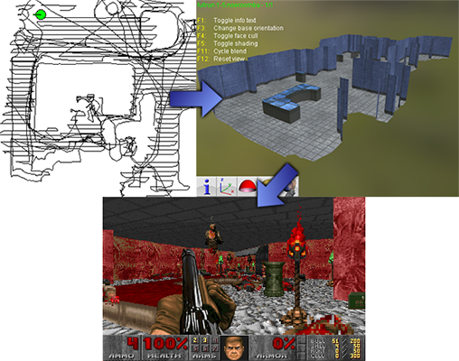
But this time around, DOOM isn’t actually running on the device being hacked. Instead, the Roomba 980 that [Rich Whitehouse] has doing his bidding is being used to generate new DOOM levels based on the maps it makes of rooms while going about its business. To be fair they’re pretty simplistic maps, and most of us don’t live in a home quite palatial enough to even fill out shareware trial of id Software’s classic, but it’s still a neat trick.
 For those who might not be up to date with the latest and greatest in the world of robotic helpers, newer model Roomba vacuums are equipped with a camera and the ability to generate 3D maps of its environment using a technique called Vision Simultaneous Localization and Mapping (VSLAM). Ostensibly this capability is used to create accurate maps of hazards in the cleaning area, but of course it did set off some privacy alarm bells when introduced due to the possibility that scans of users homes could end up being used for nefarious purposes. Roomba manufacturer iRobot swears they aren’t doing anything suspect with the data their robots collect while traveling through the user’s home, but that hasn’t stopped [Rich] from using the technology as a portal to Hell.
Using “DOOMBA”, the user is able to download the mapping data off of their Roomba 980 (it might work on other models, but hasn’t been tested yet) over the local network and import it into Noesis, a 3D model viewing program developed by [Rich]. The imported map is essentially just a 2D diagram of the home’s floor plan, which on its own wouldn’t make for a terribly interesting DOOM level, so the software will take the liberty of seeding it with weapons, baddies, and all the other varied delights of the netherworld. The user can fiddle around with these settings to try and fine-tune their homespun hellscape, or just let “DOOMBA” randomize it all so they can get on with the ripping and tearing.
If you’ve got Roomba in hand but aren’t a DOOM fan, have no fear. We’ve seen plenty of hacks and mods for everyone’s favorite house-cleaning hockey puck which happen to be of the non-demonic variety. If you just can’t get enough DOOM, stick around for tomorrow’s 25th anniversary celebration article. You will want to copy the banner art and use it as your new desktop background.
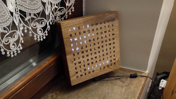
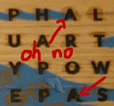 [watsaig] decided to fill all of the letters with epoxy to achieve a flat finished surface that also served as diffuser for the LEDs. To avoid using an unsightly stencil font, the centers (the cut out portion) of letters like O, A, and R had to be placed by hand. Unfortunately his turned out quite badly. When using a squeegee method to work epoxy into the letters, the inserts tended to shift, ruining the face plate.
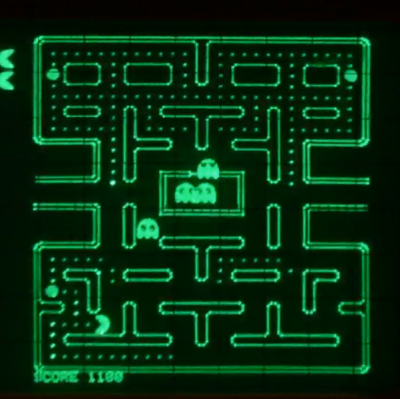 Using a CRT oscilloscope in X-Y mode as a vector display, the console faithfully reproduces some classic games, most of which, curiously enough, were not originally vector games. There are implementations of the Anaconda, RetroRacer, and AstroLander minigames from Timesplitter 2. There are also versions of Pac-Man, Tetris, and even Super Mario Brothers. Most of the games were prototyped in JavaScript before being translated into assembly and placed onto EEPROM external cartridges, to be read by the ATMega128 inside the console. Sound and music are generated using the ATMega’s hardware timers, with a little help from a reverse-biased transistor for white noise and a few op-amps.