Resurrecting PONG, One Jumper Wire At A Time

Between 1976 and 1978, over one million Coleco Telstar video game consoles were sold. The Killer App that made them so desirable? PONG. Yep, those two paddles bouncing a ball around a blocky tennis court were all the rage and helped usher in a new era. And as [Dave] of Dave’s Garage shows us in the video below the break, the bringing the old console back to life proved simpler than expected!

Thankfully, the console is built around what [Dave] quite aptly calls “PONG on a chip”, the General Instrument AY-3-8500 which was designed to make mass production of consoles possible. The chip actually contains several games, although PONG was the only one in use on the Coleco.

After removing the CPU from the non-functional console, [Dave] breathed life into it by providing a 2 MHz clock signal that was generated by an Arduino, of all things. A typical 2N2222 amplifies the audio, and a quick power up showed that the chip was working and generating audio.

Video is smartly taken care of just as it was in the original design, by combining various signals with a 4072 OR gate. With various video elements and synchronization patterns combined into a composite video signal, [Dave] was able to see the game on screen, but then realized that he’d need to design some “paddles”. We’ll leave that up to you to watch in the video, but make sure to check the comments section for more information on the design.

Is a breadboarded PONG console not retro enough for you? Then check out this old school mechanical version that was found languishing in a thrift store.

Continue reading “Resurrecting PONG, One Jumper Wire At A Time”

photograph of custom PCB assembly of NE555-based electronic dice

NE555-Based Electronic Dice

It has become a bit of a running joke in the Hackaday community to suggest that a project could or should have been done with a 555 timer. [Tim] has rather taken this to heart with his latest Electronic Dice project, which uses three of the venerable devices.

If three seems like a lot of 555s to make an electronic die, then it may be worth considering that the last time we shared his project he was using 22 of them! Since then, [Tim] has been busy optimising his design, whilst keeping within the constraints of an old-school through-hole soldering kit.

Maybe the most surprising thing about this project is the purpose to which the NE555 devices are pressed. Rather than using them for their famous oscillation properties, they are in actual fact just being used as Schmitt Triggers to clean up the three-phase ring oscillator that is constructed from discrete transistors and passives.

scope trace of the electronic dice ring oscillator
Simulation trace of the three-phase ring oscillator before Scmitt Trigger stages

The ring oscillator cleverly produces three phase-shifted square waves such that a binary combination of the three phases offers six unique states. Six being the perfect number for a dice throw, all that then remains is to figure out which LEDs need to be switched on in which state and wire them up accordingly.

To “roll” the dice, a push-button powers up the oscillator, and stops it again when it is released, displaying the random end-state on the LEDs.

It can be fun to see what can be done using old technology, and educational to try to optimise a design down to the fewest parts possible.

[Tim]’s earlier project is here if you want to see how the design has evolved. The documentation on both of these iterations is excellent and well worth a read.

Continue reading “NE555-Based Electronic Dice”

Old-School Video Switching Levels Up With Modern USB Control

Video effects and mixing are done digitally today, but it wasn’t always so. When analog ruled the video world, a big switch panel was key to effective results.

VIdeo like this was the result of combining different analog feeds with different effects. The better the hardware, the more was possible.

Devices like [Glen]’s Grass Valley Series 300 Crosspoint Switch Panel were an important part of that world. With tools like that, a human operator could set up a composited preview feed in true WYSIWYG style, and switch to live on cue. All done with relatively simple CMOS ICs and buttons. Lots and lots of buttons.

[Glen] reverse engineers the panel to show how it works, and most of the heavy lifting is done by the MC14051B analog multiplexer/demultiplexer, and the MC14532B 8-bit priority encoder. Once that’s figured out, the door is open to modernizing things a little by using a microcontroller to drive the device, turning it into a USB peripheral.

With a little design work, [Glen] builds a PCB around the EFM8UB2 8-bit microcontroller to act as a USB peripheral and control the switch panel, taking care of things like key scanning and lamp control. The last step: a GUI application for monitoring and controlling the panel over USB.

This isn’t [Glen]’s first time interfacing to vintage video mixing and switching, and as many of us know it’s sometimes tricky work to interface to existing hardware. We covered his earlier video switcher project using hardware that was not nearly as easy to work with as this one.

Printed Propeller Blades Repair Indoor Flyer

Fair warning for readers with a weak stomach, the video below graphically depicts an innocent rubber band airplane being obliterated in mid-air by a smug high-tech RC helicopter. It’s a shocking display of airborne class warfare, but the story does have a happy ending, as [Concrete Dog] was able to repair his old school flyer with some very modern technology: a set of 3D printed propeller blades.

Now under normal circumstances, 3D printed propellers are a dicey prospect. To avoid being torn apart by the incredible rotational forces they will be subjected to, they generally need to be bulked up to the point that they become too heavy, and performance suffers. The stepped outer surface of the printed blade doesn’t help, either.

But in a lightweight aircraft powered by a rubber band, obviously things are a bit more relaxed. The thin blades [Concrete Dog] produced on his Prusa Mini appear to be just a layer or two thick, and were printed flat on the bed. He then attached them to the side of a jar using Kapton tape, and put them in the oven to anneal for about 10 minutes. This not only strengthened the printed blades, but put a permanent curve into them.

The results demonstrated at the end of the video are quite impressive. [Concrete Dog] says the new blades actually outperform the originals aluminum blades, so he’s has to trim the plane out again for the increased thrust. Hopefully the extra performance will help his spindly bird avoid future aerial altercations.

On the electrically powered side of things, folks have been trying to 3D print airplane and quadcopter propellers for almost as long as desktop 3D printers have been on the market. With modern materials and high-resolution printers the idea is more practical than ever, though it’s noted they don’t suffer crashes very well.

Continue reading “Printed Propeller Blades Repair Indoor Flyer”

Audio Amp Puts VFDs To Work In An Unusual Way

It’s safe to say that most projects that feature a VFD emphasize the “D” aspect more than anything. Vacuum fluorescent displays are solid performers, after all, with their cool blue-green glow that’s just the right look for lots of retro and not-so-retro builds. But that doesn’t mean there aren’t applications that leverage the “V” aspect, such as this nifty audio preamp using VFDs as active components.

The inspiration behind [JGJMatt]’s build came from the Korg Nutube line of VFD-based low-voltage dual-triode vacuum tubes. Finding these particular components a little on the expensive side, [JGJMatt] turned to the old standby DM160 VFD indicator tube, which is basically just a triode, to see how it would fare as an amp. The circuit takes advantage of the low current and voltage requirements of the VFDs — the whole thing runs from a USB boost converter — by wedging them between a 2N3904 input stage and a 2N2007 MOSFET output. There’s a mix of SMD and through-hole components on the custom-etched PCB, with a separate riser card to show off the VFDs a little bit through the front panel of the 3D printed case.

All in all, we find this little amp pretty cool, and we love the way it puts a twist on the venerable VFD. We’ve seen similar VFD amps before, but this one’s fit and finish really pays off.

A Wheatstone Bridge Matches Your Pots

Sometimes the simplest hacks can be the most useful or ingenious, and such is the case with [Keri Szafir]’s method of ensuring that potentiometers used in audio devices are matched. If you consider a typical stereo amplifier for a moment, you’ll see two amplifiers in one box with a single volume control. Two channels, one knob? Volume knobs are ganged stereo potentiometers.

All potentiometers are not created equal, and particularly in the cheaper devices they may not have a consistently matched resistance across both pots and across their travel. This messes up the stereo balance, so naturally it’s worth selecting a part with good matching. [Keri] selects them not with his golden ears, but by wiring both pots together as a Wheatstone bridge. A meter between the two wipers would detect any current due to a mismatch.

A Wheatstone bridge is one of those handy circuits that has plenty of uses in both AC and DC measurements. We probably see them most often in a strain gauge.

A dekatron-based clock with a GPS receiver and a plastic dinosaur on top

Dekatron Clock Tells The Time, Sans Semiconductors

Over the years, there have been several memory and display technologies that served a particular niche for a while, only to be replaced and forgotten when a more suitable technology came along. One of those was the dekatron: a combination memory and display tube that saw some use in the 1950s and ’60s but became obsolete soon after. Their retro design and combined memory/display functionality make them excellent components for today’s clock hackers however, as [grobinson6000] demonstrates in his Dekaclock project.

A dekatron tube is basically a neon tube with ten cathodes arranged in a circle. Only one of them is illuminated at any time, and you can make the tube jump to the next cathode by applying pulses to its pins. The Dekaclock uses the 50 Hz mains frequency to generate 20 ms pulses in one tube; when it reaches 100 ms, it triggers the next tube that counts hundreds of ms, which triggers another one that counts seconds, and so on with minutes and hours.

The Dekaclock uses no semiconductors at all: the entire system is built from glass tubes and passive components. However, [grobinson6000] also built an auxiliary system, full of semiconductors, that makes the clock a bit easier to use. It sits on top of the Dekaclock and automatically sets the correct time using a GPS receiver. It also keeps track of the time displayed by the dekatrons, and tells you how far they have drifted from their initial setting.

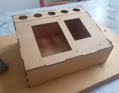
Both systems are housed in sleek wooden cases that perfectly fit the tubes’ retro aesthetic. [grobinson6000] was inspired to make the Dekaclock after watching another dekatron clock we featured earlier, and designed the GPS receiver to work alongside it. Dekatrons are surprisingly versatile devices: you can use them to make anything from internet speed gauges to kitchen timers.

Continue reading “Dekatron Clock Tells The Time, Sans Semiconductors”