Copy Protection In The 80s, Showcased By Classic Game Dungeon Master

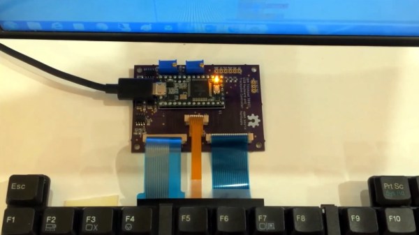
Making a copy of a purchased game used to be as simple as copying a disk. As the game industry grew, so did fear of revenue loss which drove investment in countermeasures. These mainly consisted of preventing the easy duplication of magnetic diskettes, or having users jump through tiresome hoops like entering specific words from the printed manual. These measures rarely posed much of a challenge to the dedicated efforts of crackers, but the copy protection in the classic 80s game Dungeon Master for the Atari ST and Amiga was next-level. It implemented measures that went well beyond its contemporaries, and while it was eventually defeated, it took about a year to happen. In an era where games were cracked within days or even hours of release, that was remarkable.

Dungeon Master was a smash hit at the time, and while the details of its own brand of what we would now call DRM may not be new, this video presentation by [Modern Vintage Gamer] (YouTube link) does a wonderful job of stepping through everything it did, and begins with an informative tour of copy protection efforts of the era for context.

The video is embedded below, but if you’d like to skip directly to the details about Dungeon Master, that all starts just past eight minutes in. What we now call DRM clearly had roots that preceded the digital world of today; an absurd timeline in which even cat litterboxes can have DRM.

Continue reading “Copy Protection In The 80s, Showcased By Classic Game Dungeon Master”

This Tiny TFT Pendant Is Digital Jewelry

Hackers have a multitude of skills, many are well-versed in the ways of all things that blink and flash. These abilities have often be applied to the field of jewelry and human adornment, and many LEDs have been employed in this work. [Deshipu] has been attempting something a touch different however, by constructing a tiny TFT pendant.

The basic idea is not dissimilar from those USB photo keychains of recent history. A SAMD21 Cortex M0+ serves as the brains of the operation, with the tiny microcontroller being soldered to a custom PCB that makes up the body of the pendant. A ST7735S TFT LCD screen is then attached to act as the display. Charging and delivery of images is done over USB, which can be handled natively by the SAMD21.

Currently, the pendant is capable of displaying 16-color BMPs, with the intention to create a converter for animated GIFs in the pipeline. Potential upgrades also involve creating a larger battery pack to sit behind the wearer’s neck, as currently the device has just 8 mAh to work with.

It’s a nicely designed piece, with the pendant appearing barely bigger than the screen itself. It’s not the first time we’ve seen a hacker take on a pendant, and we’re sure it won’t be the last. If you’ve got the goods, be sure to hit up the tip line. 

The PewPew Console Is Coming To EuroPython 2019

EuroPython is a community-run developer conference, which began back in Belgium in 2002. In 2019, it’s happening in Basel, Switzerland from July 8 to 14, and there’s a special surprise in store for attendees this year. Conference attendees with be provided with a PewPew console for their hacking pleasure!

An earlier version of the PewPew handheld. There have been many and varied revisions of the hardware.

We’ve featured the project before on these hallowed pages; the earlier PewPew Featherwing console was a finalist in the 2017 Hackaday Prize Best Product Competition. At EuroPython, attendees will get to tinker with a special conference edition, which is the latest version of a long line of development versions. It runs the same microcontroller – ATSAMD21E18A – as the Adafruit Trinket M0, and is programmable with CircuitPython. The conference edition comes with a large 60 mm x 60 mm LED matrix, as well as an orange PCB with blue buttons to match the color scheme of the event.

We wager that conference attendees will enjoy hacking on the handheld console, and it makes a great platform for anyone who is new to embedded development with the Python language. Similar to badges, it makes a great pack-in for patrons, and the conference should be all the more enjoyable for it!

Steamed Hams Localized Entirely Within A Printed Circuit Board

Maybe you’ve heard of a TV show called The Simpsons. Steamed Hams make a one-gag appearance in an unforgettable luncheon where Principal Skinner poker-faces his way out of a disaster with Superintendent Chalmers. Meanwhile, over on imgur, [Agumander] has put a black and white screencap from Steamed Hams in a printed circuit board.

The memory for this chip is an AT28C64, a 64 kilobit or 8 kilobyte steamed RAM. You call it a steamed RAM despite the fact that it is obviously a ROM. There is no microcontroller on this board or really anything resembling programmable logic. Everything is just logic chips. This board displays a 256×256 1 bit per pixel image over composite video. The sync is generated with the help of a 14MHz crystal and some circuitry taken from the original PONG board. Other than that, it’s just a bunch of NANDs and ORs that roll through the address space of the ROM and spit values out over a composite video port.

The build began by breadboarding everything save for a nifty solderless breadboard power adapter. Three ROM chips were programmed with different images — a cat, something to do with vaporwave, and some guy that looks like the poster from Eraserhead. Everything worked on the breadboard — yes, even at 14 MHz — so the build moved on to a printed circuit board.

The result is fantastic, and should work well on anything with a composite video port. We’re awarding bonus points for putting a socket on the ROM, simply so [Agumander] can change the image without whipping out the desoldering braid. If you need a refresher on Steamed Hams, it’s from the 7th season Simpsons episode ’22 Short Films About Springfield’.

Reverse Engineering The Sound Blaster

The first sound card to output PCM audio — the kind you need for audio samples — wasn’t the Sound Blaster. The AdLib Music Synthesizer Card could output PCM audio over software. The AdLib card also cost $200 at the time of its release. This was too much for some, and in time the Creative Labs Sound Blaster was released for the rock-bottom price of $125. This was a more capable card, and in the years since prices on the used market have gone through the roof. In 1990, you could buy a Sound Blaster for a Benjamin and a half, in 2019, prices on eBay are reaching and exceeding $400.

With the prices of used cards so high, we start to get into the territory where it starts to make sense to reverse engineer and re-manufacture the entire card. This hasn’t been done before, but that’s no matter for [Eric Schlaepfer], or [@TubeTimeUS]; he’s done crazier projects before, and this one is no different.

In reverse-engineering the Sound Blaster, there are a few necessary components. The Sound Blaster had an OPL2 chip for sound synthesis, which you can get through various vendors. The trick, though, is the microcontroller. This is really just an 8051 with a custom mask ROM.

The goal of this project is actually just to dump the ROM on the Intel 8051-alike microcontroller. This is something that’s relatively commonly done in high-tech labs, and luckily the Bay Area has [John McMaster], the guy who will take you into his lab and strip a die from its epoxy. Looking at the chip under the microscope, it was discovered the mask ROM on this chip was an implant ROM, with the ones and zeros represented by invisible ions in the substrate itself. There was no hope of reverse-engineering this chip from a purely visual inspection, but there was a sense amplifier on one of the data lines. By probing this sense amplifier while running through the address space, [Eric] was able to dump all the bytes of the ROM one bit at a time.

However, and there’s always a however, there are clone Sound Blasters out there, usually from China, and you can dump these chips if you’re lucky enough to get your hands on one. [Eric] reached out to the community and found these clone microcontrollers didn’t have the code protect bit set; dumping these was easy. This ROM was compared to the work [Eric] did with the sense amplifier, and after figuring out the order of the bits, it was found the code matched. The code was successfully cloned, and now new Sound Blasters can be made. Don’t tell eBay that, because someone is trying to sell one of [Eric]’s clone cards for $180.

All the code, files, materials, and everything needed to clone a Sound Blaster can be found in [Eric]’s GitHub, although there are a few open questions as to what’s going on in the Sound Blaster’s microcontroller. There’s a ‘secret’ 512-byte ROM on the die, and no one outside of an Intel NDA knows what it does. This could be used for a manufacturing test, but who knows. Other than that, there are a few features in the code that weren’t used, like previously unknown DSP commands, an ADPCM lookup table, and a routine that plays from SRAM without using DMA. It’s a deep dive into the inner workings of the most popular sound card of all time, and it’s quite simply amazing.

Manufacturing New Connectors For The Apollo Guidance Computer

The fiftieth anniversary of the Apollo 11 mission – the flight that first took man to the surface of the moon — is coming up. By the time this post is published, some YouTube channel will invariably be running a real-time-but-delayed-fifty-years live stream of all the mission events, culminating on the wee hours of July 20th where we wait hours for someone to figure out how to open the door.

[CuriousMarc] and space hardware collector [Jimmie Loocke] have a different type of anniversary in mind. They have an Apollo Guidance Computer sitting on a bed in a motel room, and they’re going to get it up and running by July 20th. That’s the plan, at least. This is no easy feat: the Apollo Guidance Computer looks like two 19-inch, 1U rack units, with no standardized connectors to talk to any other hardware. They’ve just figured out the hardest part of this build by making their own NASA-spec contacts. They can now connect external hardware to the AGC, probably for the first time in decades.

As it stands now, there are external ports on the gigantic bricks of aluminum enclosure that comprise the two AGC modules. These ports are just female pin headers, completely unlike any standard that can be found today. However, the folks at Samtec managed to build the male versions of these pin headers for this project. These pins fit the female sockets on one end, and are standard, square-shaped wire wrapped headers on the other. They are mounted in a milled plastic block, and after everything is wired up, [Marc] and [Jimmie] had a direct electrical connection to the Apollo Guidance Computer. The machine lives again.

There’s still a lot of work to do to get these bricks of computer up and running for the 20th, but this is fantastic progress. Already they’re single-stepping the AGC and running the P63 program that landed on the moon. Check out the video below.

Continue reading “Manufacturing New Connectors For The Apollo Guidance Computer”

Modeling The Classic 555 Timer On A Breadboard

Over the years, readers have often commented that microcontrollers (or more specifically, the Arduino) are overkill for many of the projects they get used in. The admonition that the creator “Should have used a 555” has become something of a rallying cry for those who think modern electronic hobbyists are taking the easy way out.

But what if you think even the lowly 555 timer is overkill? In that case, perhaps you’ll be interested in a recent blog post by [TheMagicSmoke], where the reader is walked through the process of creating an analog of the classic integrated circuit on a somewhat larger scale. Finally, we can replace that cheap and handy IC with a mass of wires and components.

Alright, so you’ve probably guessed that there’s no practical reason to do this. Outside of some theoretical MacGyver situation in which you needed to create a square wave using parts salvaged from devices laying around, anyway. Rather, the project is presented as a good way to become more confident with the low-level operation of electronic circuits, which is something we think everyone can agree is a good thing.

The components used include a 74S00 quad NAND gate, a LM358 dual operational amplifier, a 2N2222A transistor, and a handful of passive components. [TheMagicSmoke] not only explains how the circuit is constructed, but shows the math behind how it all works. Finally, an oscilloscope is used to verify it’s operating as expected.

We respect a hacker on a mission, just last month [TheMagicSmoke] put together a similar “back to basics” post on how to interface with an I2C EEPROM.