We’re no strangers to unusual clocks here at Hackaday, and some of our favorites make time a little more tangible like [Kyle Rankin]’s knitting clock.
Inspired by our coverage of [Siren Elise Wilhelmsen]’s knitting clock, [Rankin] decided to build one of his own. Since details on the build from the original artist were sparse, he had to reverse engineer how the device worked. He identified that a knitting clock is essentially a knitting machine with a stepper motor replacing the hand crank.
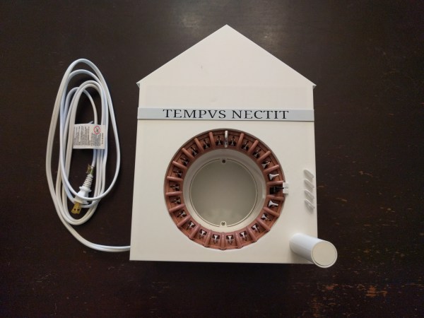
Using a Raspberry Pi with an Adafruit motor hat connected to a stepper motor and a 3D printed motor adapter, [Rankin] was able to drive the knitting machine to do a complete round of knitting every twelve hours. By marking one of the knitting pegs as an hour hand, the clock works as a traditional clock in addition to its year-long knitting task. [Rankin] says he still has some fine tuning to work on, but that he’s happy to have had the chance to combine so many of his interests into a single project.
If you’re looking for more knitting hacks, check out this knitted keyboard instrument or a knitted circuit board.
Continue reading “Tempus Nectit, A DIY Knitting Clock With Instructions”