Run A RepRap On An ESP8266

What can’t the little $5 WiFi module do? Now that [lhartmann] has got an ESP8266 controlling the motors of a 3D printer, that’s one more item to check off the list.

What’s coolest about this project is the way that [lhartmann] does it. The tiny ESP8266 has nowhere near the required number of GPIO pins, the primary SPI is connected to the onboard flash memory, and the secondary SPI is poorly documented and almost nobody uses it. So, [lhartmann] chose to use the I2S outputs.

I2S is most often an audio protocol, so this might at first seem like a strange choice. Although I2S sounds like I2C, it’s really essentially an SPI protocol with a fourth wire that alternates to designate the right or left channel. It’s actually just perfect for sending 16×2 bits of data at high data rates.

[lhartmann] takes these 32 bits and feeds them into four shift registers, producing 32 outputs from just the four I2S data lines. That’s more than enough signals to run the stepper motors. And since it updates at 192 kHz sample rate, it’s plenty fast enough to drive them.

The other side benefit of this technique is that it can work on single-board computers with just a little bit of software. Programming very complicated stepper movements then becomes just a matter of generating the right “audio” file and playing it out. [lhartmann] demonstrated this earlier with an Orange Pi. That’s pretty cool, too.

The code for turning the ESP8266 and a short handful of 74HC595s into a 3D printer controller are up on GitHub, so go check it out.

Thanks [CNLohr] for the tip!

Inventables Releases Improved X-Carve CNC Router

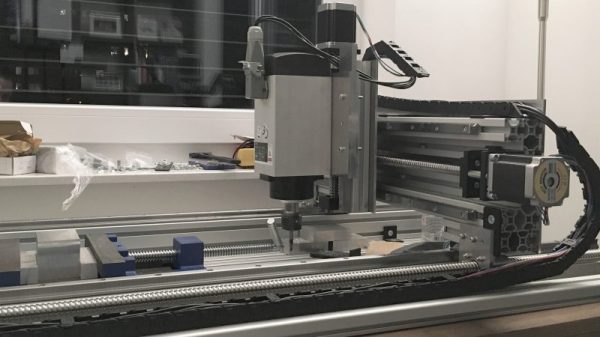
Introduced last year as an improvement on the very popular Shapeoko CNC router, the X-Carve by Inventables has grown to be a very well-respected machine in the community. It’s even better if you throw a DeWalt spindle on there, allowing you to cut almost everything that’s not steel. With a recent upgrade to the X-Carve, it’s even more capable, featuring the best mods and suggestions from the community that has grown up around this machine.

The newest iteration of the X-Carve features higher power drivers, better rigidity, and a heat sink for the spindle. That last item is an interesting bit of kit – routing takes time, and a 1¼HP motor will turn electricity into heat very effectively.

X-CarveIn addition to the 500mm square and 1000mmm square routers previously available, there’s a new, 750mm square machine available. All machines feature a new electronics box for the X-Carve, the X-Controller. This ‘brain box’ is a combined power supply, stepper driver, and motion controller built into a single box. The stepper drivers are able to supply 4A to a motor, is capable of 1/16 microstepping, and has connections for limit switches, spindle control speed, a Z probe, and outputs for vacuums or coolant systems. The underlying controller is based on grbl, making this brain box a very solid foundation for any 3-axis CNC build. The ‘brain box’ format seems to be the way the hobbyist CNC market is going, considering the whispers and rumors concerning Lulzbot selling their Taz6 brainbox independently from a 3D printer.

The new X-Carve is available now, with a fully-loaded 1000mm wide machine coming in at about $1400. That’s comparable to many other machines with the same volume, unlike the Chinese 3040 CNC machines, you don’t need to find an old laptop with a parallel port.

The Evolution Of A DIY Circuit Board Plotter

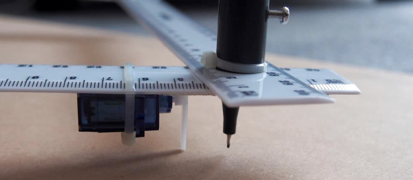
In this three part video series we watch [Dirk Herrendoerfer] go from scraps to a nice 3D printed assembly as he iterates through the design of a pen plotter for making circuit boards.

[dana] mentioned [Dirk]’s work in the comments of this post which describes a different process. Many permanent markers stick to copper well enough to last through the chemical etching process. While hand drawing definitely produces some cool, organic-looking boards, for sharp lines and SMDs it gets a bit harder; to the point where it becomes advisable to just let a robot do it.

Of course, [Dirk] was aware of this fact of life. He just didn’t have a robot on hand. He did have some electronic detritus, fishing line, an Arduino, scrap wood, brass tubes, and determination.  The first version‘s frame consisted of wooden blocks set on their ends with holes drilled to accept brass rods. The carriage was protoboard and hot glue. Slightly larger brass tubing served as bushings and guide. As primitive as it was the plotter performed admirably, albeit slowly.

The second version was a mechanical improvement over the first, but largely the same. The software got a nice improvement. It worked better and had some speed to it.

The latest version has some fancy software upgrades; such as acceleration. The frame has gone from random bits of shop trash to a nicely refined 3D printed assembly. Even the steppers have been changed to the popular 28BYJ-48 series. All the files, software and hardware, are available on GitHub. The three videos are viewable after the break. It’s a great example of what a good hacker can put together for practically no money.

Continue reading “The Evolution Of A DIY Circuit Board Plotter”

Impressive Junkyard CNC Made From Fancy Garbage

We’ll just come out and say it, [reboots] has friends with nice garbage. Sure, some of us have friends who are desperately trying to, “gift,” us a CRT monitor, hope dropping like a rock into their stomach when they realize they can’t escape the recycling fee.  [reboots] has friends who buy other people’s poorly thought out CNC projects and then gift him with the parts.

After dismantling the contraption he found himself with nice US and Japanese made linear motion components. However, he needed a CNC controller to drive it all. So he helped another friend clean out their garage and came away with a FlashCut CNC controller.

Now that he had a controller and the motion components whirring nicely, he really needed a frame to put it all in. We like to imagine that he was at a friend’s  barbeque having a beer. In one corner of the yard was an entire Boeing 747.  A mouldering scanning electron microscope with a tattered and faded blue tarp barely covering its delicate instrumentation sat in another corner. Countless tech treasures were scattered about in various states. It was then that he spotted a rusting gamma ray spectrometer in the corner that just happened to have the perfect, rigid, gantry frame for his CNC machine.

Of course, his friend obliged and gladly gave up the spectrometer. Now it was time to put all together. The gantry was set on a scavenged institutional door. The linear motion frames were bolted in place. Quite a few components had to be made, naturally, of scrap materials.

spindletest2Most people will start by using a handheld router for the spindle. The benefits are obvious: they’re inexpensive, easy to procure, and generally come with mounts. But, there are some definite downsides, one of the most glaring of which is the lack of true speed control.

Even routers that allow you to adjust the speed (a fairly common feature on new models) generally don’t actually regulate that speed. So, you end up with a handful of speed settings which aren’t even predictable under load. Furthermore, they usually rely on high RPMs to do their work. For those reasons, handheld woodworking routers aren’t the best choice for a mill that you intend to cut metal with.

[reboots] noticed this problem while building this machine and came up with an inexpensive way to build a speed-controlled spindle. His design uses a brushless DC motor, controlled through a hobby ESC (electronic speed control), which uses a belt to drive the spindle. The spindle itself is mounted using skateboard bearings, and ends in an E11 collet (suitable for light machining in aluminum).

With the ESC providing control of the brushless motor, he’s able to directly control the spindle speed via software. This means that spindle speeds can be changed with G-code, allowing for optimized feeds and speeds for different operations. The belt-drive increases torque while separating the motor from the spindle, which should keep things cool, and reduce rotating mass on the spindle itself. Now all [reboots] needs to do is add a DIY tool changer!

How Accurate Is Microstepping Really?

Stepper motors divide a full rotation into hundreds of discrete steps, which makes them ideal to precisely control movements, be it in cars, robots, 3D printers or CNC machines. Most stepper motors you’ll encounter in DIY projects, 3D printers, and small CNC machines are bi-polar, 2-phase hybrid stepper motors, either with 200 or — in the high-res variant — with 400 steps per revolution. This results in a step angle of 1.8 °, respectively 0.9 °.

Can you increase the resolution of this stepper motor?

In a way, steps are the pixels of motion, and oftentimes, the given, physical resolution isn’t enough. Hard-switching a stepper motor’s coils in full-step mode (wave-drive) causes the motor to jump from one step position to the next, resulting in overshoot, torque ripple, and vibrations. Also, we want to increase the resolution of a stepper motor for more accurate positioning. Modern stepper motor drivers feature microstepping, a driving technique that squeezes arbitrary numbers of microsteps into every single full-step of a stepper motor, which noticeably reduces vibrations and (supposedly) increases the stepper motor’s resolution and accuracy.

On the one hand, microsteps are really steps that a stepper motor can physically execute, even under load. On the other hand, they usually don’t add to the stepper motor’s positioning accuracy. Microstepping is bound to cause confusion. This article is dedicated to clearing that up a bit and — since it’s a very driver dependent matter — I’ll also compare the microstepping capabilities of the commonly used A4988, DRV8825 and TB6560AHQ motor drivers.

Continue reading “How Accurate Is Microstepping Really?”

Much More Than A Desktop Mill: The DIY VMC Build

A VMC (vertical machining center) is essentially a CNC vertical milling machine on steroids. Many CNC mills are just manual milling machines that have been converted to CNC control. They work nicely, but have a number of drawbacks when it comes to real world CNC milling: manual tool changes, lack of chip collection, lack of coolant containment, and backlash issues (which a manual machinist normally compensates for).

These problems are solved with a VMC, which will usually have an automatic tool changer, and an enclosure to contain coolant and wash chips down into a collection pan. They are, however, very expensive, very big, and very heavy. Building one from scratch is a massive undertaking, but one which [Chris DePrisco] was brave enough to take on.

Continue reading “Much More Than A Desktop Mill: The DIY VMC Build”

Hands-On The Shaper Origin: A Tool That Changes How We Build

I bet the hand saw really changed some things. One day you’re hacking away at a log with an ax. It’s sweaty, awful work, and the results are never what you’d expect. The next day the clever new apprentice down at the blacksmith’s shop is demoing his beta of his new Saw invention and looking for testers, investors, and a girlfriend. From that day onward the work is never the same again. It’s not an incremental change, it’s a change. Pure and simple.

This is one of those moments. The world of tools is seeing a new change, and I think this is the first of many tools that will change the way we build.

Like most things that are a big change, the components to build them have been around for a while. In fact, most of the time, the actual object in question has existed in some form or another for years. Like a crack in a dam, eventually someone comes up with the variation on the idea that is just right. That actually does what everything else has been promising to do. It’s not new, but it’s the difference between crude and gasoline.

My poetic rasping aside, the Shaper Origin is the future of making things. It’s tempting to boil it down and say that it’s a CNC machine, or a router. It’s just, more than that. It makes us more. Suddenly complex cuts on any flat surface are easy. Really easy. There’s no endless hours with the bandsaw and sander. There’s no need for a 25,000 dollar gantry router to take up half a garage. No need for layout tools. No need to stress about alignment. There’s not even a real need to jump between the tool and a computer. It can be both the design tool and the production tool. It’s like a magic pencil that summons whatever it draws. But even I had to see it to believe it.

Continue reading “Hands-On The Shaper Origin: A Tool That Changes How We Build”