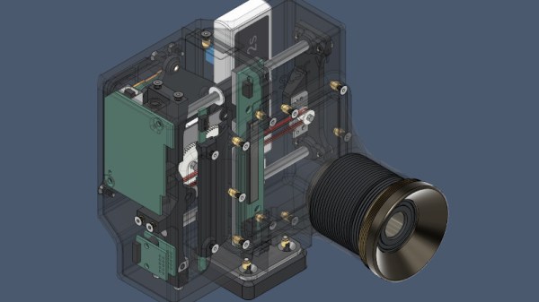
The megapixel wars of a decade ago saw cameras aggressively marketed on the resolution of their sensors, but as we progressed into the tens of megapixels it became obvious even to consumers that perhaps there might be a little more to the quality of a digital camera than just its resolution. Still, it’s a frontier that still has a way to go, even if [Yunus Zenichowski]’s 489 megapixel prototype is a bit of an outlier. As some of you may have guessed it’s a scanner camera, in which the sensor is a linear CCD that is mechanically traversed over the focal plane to capture the image line by line.
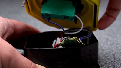
In the 3D printed shell are the guts of a cheap second-hand Canon scanner, and the lens comes from a projector. Both these components make it not only one of the highest resolution cameras we’ve ever brought you, but also by no means the most expensive. It’s definitely a work in progress and the results of a sensor designed for the controlled environment of a document scanner being used with real-world light leave something to be desired, but even with the slight imperfections of the projector lens it’s still a camera capable of some fascinating high-resolution photography. The files are all available, should you be interested, and you can see it in action in the video below the break.
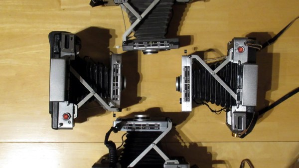
It’s by no means the first scanner camera we’ve brought you, though some of the earlier projects now have dead links. It is however easily the one with the highest resolution.