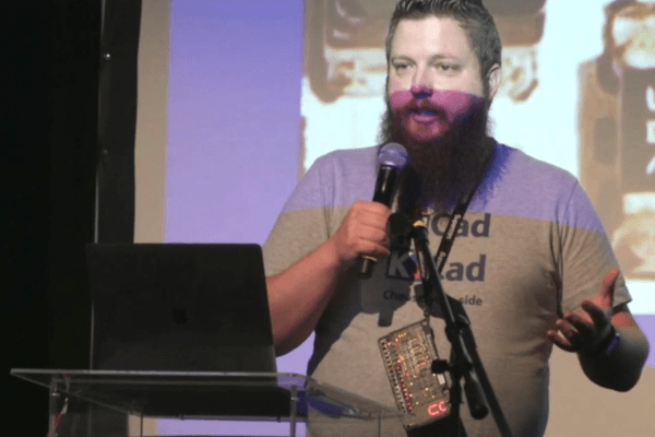
Michael Whiteley (aka [compukidmike]) is a badgelife celebrity. Together, he and his wife Katie make up MK Factor. They have created some of the most popular electronic conference badges. Of course, even experts make mistakes and run into challenges when they dare to push the envelope of technology and delivery schedules. In his Supercon 2022 talk, There’s No Rev 2: When Badgelife Goes Wrong, Mike shares details from some of his worst badge snafus and also how he managed to gracefully pull them back from the edge of disaster.
Living the Badgelife
Attendees at the world’s largest hacker convention, DEF CON in Las Vegas, had already become accustomed to receiving and wearing very cool and novel admission tokens, more properly known as badges. Then in 2006, at DEF CON 14, everything changed. Designed by Joe Grand, the first electronic DEF CON badge was a circuit board featuring a tiny PIC microcontroller, two LEDs, and a single pushbutton. Badgelife was born.
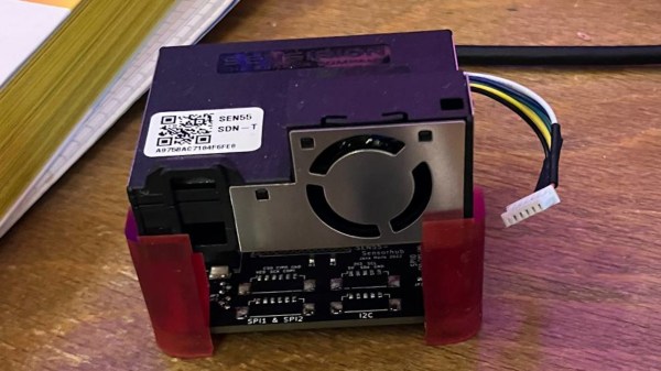
DEF CON 30 Humans Sampling Board
Mike begins his war stories with one about the DEF CON 30 badge. This was a herculean project with 25,000 badges being produced on a short timeline in the ever-changing chaos of a semiconductor supply-chain meltdown. Even though many regard it as one of the best DEF CON badges ever made, the DC30 badge posed a number of challenges to its creators. Microcontrollers were in short supply during 2021 and 2022 forcing the badge team to keep an eye on component vendor supplies in order to snipe chips as soon as they appeared in stock. The DC30 badge was actually redesigned repeatedly as different microcontrollers fluctuated in and out of supply. Continue reading “Supercon 2022: Michael Whiteley Saves The Badge”
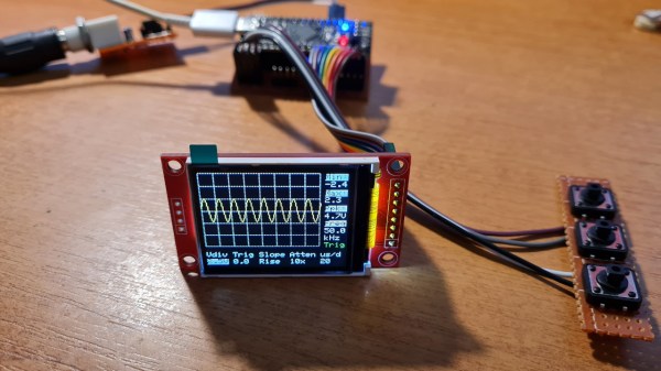
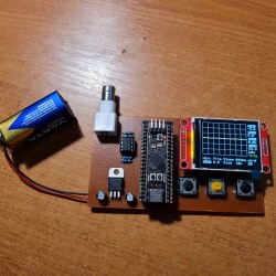 It’s hard to overshadow just how easy this scope is to build, use, and hack on. You really don’t need much in the way of parts, a protoboard will do, though you can also etch or order