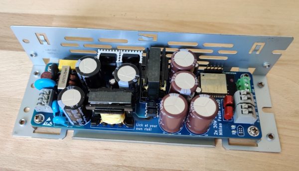
Ask Hackaday: Is USB Robust Enough?

Earlier this month a single person pleaded guilty to taking down some computer labs at a college in New York. This was not done by hacking into them remotely, but by plugging a USB Killer in one machine at a time. This malicious act caused around $58,000 in damage to 66 machines, using a device designed to overload the data pins on the USB ports with high-voltage. Similar damage could have been done with a ball-peen hammer (albeit much less discreetly), and we’re not here to debate the merits of the USB Killer devices. If you destroy property you don’t own you should be held accountable.

But the event did bring an interesting question to mind. How robust are USB ports? The USB Killer — which we’ve covered off and on through the years —  is billed as a “surge testing” device and operates by injecting -200 volts DC on the data lines of the USB connection. Many USB ports are not protected against this and the result is permanent damage to the computer hardware. Is protection for these levels of abuse necessary or would it needlessly add cost to our machines?

A chip like the TPD4S014 has ESD protection on the data lines that is rated up to +/- 1500 volts, clamping to ground to dissipate the energy. It’s a solution that should protect against repeated spikes on the data lines, as well as short circuits on the power lines and over/undervoltage situations.

ADUM4160 Functional Diagram

The ADuM4160 is an interesting step up from this. It’s designed to provide isolation between a USB host and the device connected to it. Rather than relying on clamping, this chip implements isolation through air core transformers. Certainly this would be overkill to install in every product, but for those of use building and testing USB devices this would save you from “Oops, wrong USB cable” moments at the work bench.

Speaking of accidents at the bench, there is certainly a demand for USB isolation outside of what’s built into our computers. Earlier this year we saw a fantastic take on a properly-designed USB power strip. Among the goals were current limiting, undervoltage protection, and a proper power disconnect switch for each port. The very need to design your own reminds us that consumer manufacturers are often lazy in their USB design. “Use a USB hub” is bad advice for protection at the workbench since quality of design varies so wildly.

We would be interested in hearing from anyone who has insight on standards applying to equipment continuing to survive over current or over voltage events and remain functional. There are standards like UL-60950 that should apply to USB. But that standard includes language about failing safe for the operator, not necessarily remaining functional:

After abnormal operation or a single fault (see 1.4.14), the equipment shall remain safe for an OPERATOR in the meaning of this standard, but it is not required that the equipment should still be in full working order. It is permitted to use fusible links, THERMAL CUT-OUTS, overcurrent  protection devices and the like to provide adequate protection.

So, we’re here to ask you, the readers of Hackaday. Are our USB devices robust enough? Do you have a go-to USB protection chip, part, or other circuit you like to use? Have you ever accidentally killed a USB host device (if so, how)? Do you have special equipment that you depend on when developing projects involving USB? Let us know what you think in the comments below.

Driving A 16×2 LCD With Voltage Modulation

The basic 16×2 LCD is an extremely popular component that we’ve seen used in more projects than we could possibly count. Part of that is because modern microcontrollers make it so easy to work with; if you’ve got an I2C variant of the display, it only takes four wires to drive it. That puts printing a line of text on one of these LCDs a step or two above blinking an LED on a digital pin on the hierarchy of beginner’s electronics projects.

What’s that? Even four wires is too many? In that case, you might be interested in this hack from [Vinod] which shows how you can drive the classic 16×2 with data and power on the same pair of wires. You’ll still need a microcontroller “backpack” for the LCD to interpret the modulated voltage, but if you’ve got an application for a simple remote display, this is definitely worth checking out.

The basic idea is to “blink” the 5 V line so quick that a capacitor on the LCD side can float the electronics over the dips in voltage. As long as one of the pins of the microcontroller is connected to the 5 V line before the capacitor, it will be able to pick up when the line goes low. With a high enough data rate and a large enough capacitor as a buffer, you’re well on the way to encoding your data to be displayed.

For the transmitting side, [Vinod] is using a Python script on his computer that’s sending out the text for the LCD over a standard USB to UART converter. That’s fed into a small circuit put together on a scrap of perfboard that triggers a MOSFET off of the UART TX line.

We actually covered the theory behind this technique years ago, but it’s always interesting to see somebody put together a real-world example. There might not be too many practical uses for this trick in the era of dirt-cheap microcontrollers bristling with I/O, but it might make a fun gag at your hackerspace.

Continue reading “Driving A 16×2 LCD With Voltage Modulation”

Make That Special Cup Of Coffee By Completely Tweaking The Coffee Machine

An interesting part of working on the Building Management and Control (BMaC) project – as previously covered on this site – was the reverse-engineering and ultimately the gaining of full control over the coffee machines at the office. Not the boring filter coffee machines, mind you, but the fully automatic espresso machine type that grinds beans, makes coffee, adds milk, and much more. Depending on one’s budget, naturally.

These little marvels of engineering contain meters of tubing, dozens of sensors, valves, ceramic grinders, and heating elements. The complexity of this machinery made us think that maybe there was more that we could do with these machines beyond what their existing programming and predefined products would allow. Naturally, there was.

Continue reading “Make That Special Cup Of Coffee By Completely Tweaking The Coffee Machine”

Charge All Your Batteries With USB PD

USB-C has been around for a while, and now that it can charge phones and Macbooks and Thinkpads, the hackers are starting to take note of power adapters that can supply lots of current. [Alex] was turned on to USB-C after he charged a laptop, Nintendo Switch, and phone with one power adapter. This led him to create a USB-C battery charger for all your LiPos.

The high-level design of this project is simply a board with a USB C port on one end, an XT60 plug on the other, and some support for balance leads. Plug this board into a USB C adapter, plug a battery in, and the battery will charge automagically. The only UI is an RGB LED. It’s difficult to imagine a battery charger that’s easier to use.

For the electronics, [Alex] is using an STM32G0 for the smarts of the device, which includes handling the USB PD spec. This gives the charger 20 Volts to play with, and this is then regulated and sent into the battery. Right now, this board will charge 2-4c batteries. That’s a good enough proof of concept to charge some quadcopter batteries, or just as a really simple way to charge some LiPo cells.

Component Shelf Life: How To Use All That Old Junk

There are two types of Hackaday readers: those that have a huge stock of parts they’ve collected over the years (in other words, an enormous pile of junk) and those that will have one a couple of decades from now. It’s easy to end up with a lot of stuff, especially items that you’re likely to use in more than one design; the price breakpoints at quantities of 10 or 100 of something can be pretty tempting, and having a personal stock definitely speeds the hacking process now that local parts shops have gone the way of the dinosaur. This isn’t a perfect solution, though, because some components do have shelf-lives, and will degrade in some way or another over time.

If your stash includes older electronic components, you may find that they haven’t aged well, but sometimes this can be fixed. Let’s have a look at shelf life of common parts, how it can be extended, and what you can do if they need a bit of rejuvenation.

Continue reading “Component Shelf Life: How To Use All That Old Junk”

Need A Small Keyboard? Build Your Own!

If you want keyboards, we can get you keyboards. If you want a small keyboard, you might be out of luck. Unless you’re hacking Blackberry keyboards or futzing around with tiny tact switches, there’s no good solution to small, thin, customization keyboards. There’s one option though: silicone keyboards. No one’s done it yet, so I figured I might as well.

Unfortunately, there is no readily available information on the design, construction, or manufacture of custom silicone keypads. There is a little documentation out there, but every factory that does this seems to have copy and pasted the information from each other. Asking a company in China about how to do it is a game of Chinese Whispers. Despite this, I managed to build a custom silicone keypad, and now I’m sharing this information on how to do it with you.

Continue reading “Need A Small Keyboard? Build Your Own!”

Add-Ons Go Electroluminescent

It’s that time of the year again, and once more we’re faced with the latest innovations in Badgelife, the movement to explore the artistic merits of electronics and manufacturing. This is an electroluminescent printed circuit board, and it’s some of the finest work we’ve seen. It’s also a Shitty Add-On that glows blue.

The process for applying an electroluminescent coating to printed circuit boards is, surprisingly, something we’ve covered before. Late last year, [Ben Krasnow] delved deep into a DIY EL display. The process is expensive, but all the products come from a company called Lumilor. The first step in this process is applying a thin conductive coating on a substrate with an airbrush. Since the entire idea of printed circuit boards is to have a layer of conductive material etched into any shape you want, the simple circuit board is the idea experimental platform for playing with EL displays. Traditionally, EL displays were made entirely with a silk screen process, like [Fran]’s ongoing attempt to recreate the Apollo DSKY display.

The electronics for this badge are simply a Microchip MIC4832 EL Driver, which converts the 3.something volts from the add-on header into 100 or so Volts AC at hundreds of Hz. This is a single-chip solution to driving EL displays, and the only other parts you need are an inductor, diode, and a few caps and resistors. An ATtiny85 can be used to blink the circuits, or, alternatively, you could copy [Ben]’s work and build a character EL display.

The process of applying an electroluminescent coating to a PCB does require a spray gun or airbrush, and the chemicals are a bit expensive. This, though, is pushing the boundaries of what can be done with artistic PCBs. It’s new applications of technology, simply as wearable electronics. It’s the best example of the possibilities of the medium and some of the best work that’s come out of the Badgelife scene.