Game cartridges are generally seen as a read-only medium with the contents as immutable as text chiseled into a granite slab, and with accompanying save files on the cartridge surviving for generations. The unfortunate truth is that as with any media storage, cartridges can and do fail, and save files are often just ethereal bits in battery-backed SRAM. This makes being able to copy not only the game data but also the save files off these cartridges essential. Projects like the Open Source Cartridge Reader by [sanni] make this something that everyone can do.
Intended to be a kind of Swiss Army knife of game cartridges, many game systems are supported directly, and many others via (user-created) adapters. A how-to-build tutorial is provided on the project wiki, though anyone interested in building such a system would do well to look at the expected price tag on the BOM page, which comes in at $134. A recent video by [Kytor Industries] (also included below) demonstrates how to assemble one of these systems, including some modding of the preassembled components.
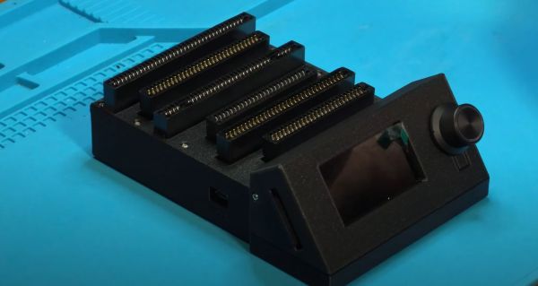
The main components are the Arduino Mega 2560 Pro MCU module, a Makerbase assembly with LCD, control knob, and SD card slot, an SI5351-based clock generator, a PIC12F629 MCU (for snesCIC and handling SNES DRM) and a lot of pin headers and card edge connectors for specific cartridge types. The assembly is rounded off with a surface-mounted GBA card reader and an enclosure.
One important gotcha is that some of these cartridges run on 5V, while others use 3.3V. N64 cartridges require the dedicated voltage switch to be set to 3.3V, lest 5V gets sent into the unsuspecting cartridge. Once everything is configured properly, the firmware is flashed onto the Mega 2560 Pro module. The Sanni reader is then ready to run. You can use it to dump ROMs onto SD cards, along with dumping and restoring save files and loading ROMs onto new cartridges.
(Thanks to [Roman] for the tip)
Continue reading “Building The Sanni Cartridge Reader To Back Up And Restore Games And Saves”