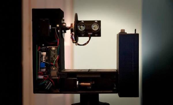
Moore’s law may have reached its physical limit for transistor density, but plenty of other technologies are still on that familiar path of getting smaller and smaller as time passes. It looks like LIDAR is no exception to this trend either. This project from [Owen] shows a fully-functional LIDAR system for about $20 and built almost entirely on top of an ESP32.
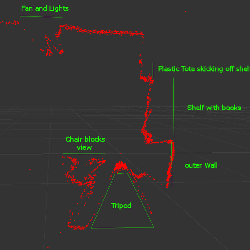
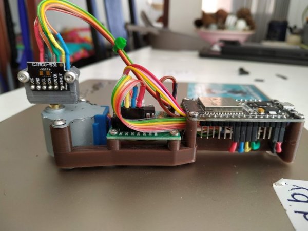
The build uses a Time-Of-Flight IR laser range sensor controlled by the ESP32, and the sensor is much smaller than even the ESP32’s footprint so it takes up very little extra space. To get it to function as a LIDAR system instead of just a simple rangefinder it does need a motor in order to rotate itself to see its entire space. Besides its small form factor and low cost, it also has a handy user interface that can run anywhere an HTML5 browser can run, making the use of the system easy and straightforward as well. All of the code is available on the project’s GitHub page.
We wouldn’t expect a system like this to be driving an autonomous car anytime soon, it’s update rate is far too slow, but its intent for small robots and even as an educational demo for learning LIDAR is second to none. If you do need a little more power in a LIDAR system but still don’t want to break the bank, we featured this impressive setup a few weeks ago.