The IKEA OBEGRÄNSAD is a pixel-style LED wall lamp that comes with a few baked-in animations, and [ph1p] improved it immensely with an ESP32 board and new firmware. The new controller provides all kinds of great new abilities, including new modes and animations, WiFi control, and the ability to send your own images or drawings to the panel. All it takes is desoldering the original controller and swapping in a programmed ESP32.
Hacking in a new controller provides a whole new range of capabilities.
Sadly, opening the unit up is a bit of a pain. It seems the back panel is attached with rivets rather than screws, but it will yield to a little bit of prying force.
The good news is that once the back panel is off, the inside of the OBEGRÄNSAD is very hackable. All the parts and connectors are easily accessible from where they are, and a nicely-labeled pin header makes a convenient attachment point for the new ESP32 board. There’s no need to disassemble any further once the back is off, and that’s always nice.
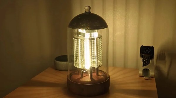
Vacuum tubes are pretty, which is why they’re often showcased externally on exquisitely-expensive home Hi-Fi hardware. But if you just want to gaze at their beauty without making any noise, why not build this vacuum tube lamp from [Noel Törjék] instead?
[Noel] got into some creative reuse with this build, with the main body consisting of a bell jar and wooden bowls. The internal structure is then created from jar lids, wire, metal sheeting, steel rods, and galvanized wire mesh. Simple modelling techniques are used to assemble the internal parts of the “valve,” including the grid and the electrodes and so on. As for light, [Noel] employed a ZigBee LED driver that he could control over his smart home setup via a Philips Hue bridge.
The final result looks like an extra-large tube. Anyone who knows what it is will spot that it’s not a real one, but they’re also exactly the audience that will appreciate it for what it is. Everyone else will probably just think you’ve taken an interest in strange art-deco replica lighthouses. It’s not the first time we’ve seen replica valves around these parts, though, and we’re sure it won’t be the last!
For many of us, the most difficult aspect of a project comes when it’s time to document the thing. Did you take enough pictures? Did you remember all the little details that it took to put it together? Should you explain those handful of oddball quirks, even though you’re probably the only person in the world that knows how to trigger them?
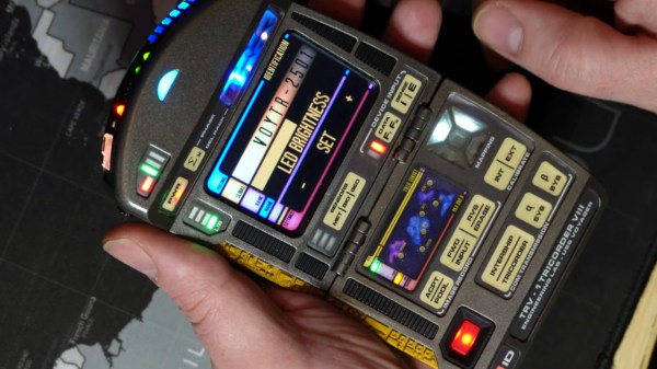
Well, we can’t speak to how difficult it was for [Mangy_Dog] to put together this training video for his incredible Star Trek: Voyager tricorder replica, but we certainly approve of the final product. Presented with a faux-VHS intro that makes it feel like something that would have been shown to cast members during the legendary run the franchise had in the 1990s, the video covers the use and operation of this phenomenal prop in exquisite detail.
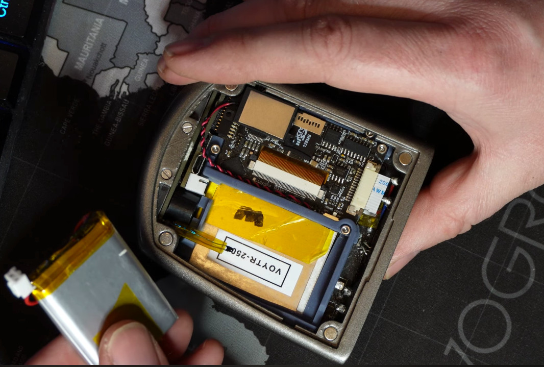
Replaceable batteries are standard again in the 2370s.
Now to be fair, [Mangy_Dog] has sold a few of his replicas to other Trek aficionados, and we’re willing to bet they went for a pretty penny. As such, maybe it’s not a huge surprise he’d need to put together a comprehensive guide on how to operate the device’s varied functions. Had this been a personal project there wouldn’t have been the need to record such a detailed walk-through of how it all works — so in that regard, we’re fortunate.
One of the most interesting things demonstrated in this video is how well [Mangy_Dog] managed to implement mundane features such as brightness and volume control without compromising the look of the prop itself. Rather than adding some incongruous switches or sliders, holding down various touch-sensitive buttons on the device brings up hidden menus that let you adjust system parameters. The project was impressive enough from the existing images and videos, but seeing just how deep the attention to detail goes is really a treat.
Previously we took a look at some of the work that [Mangy_Dog] has put into these gorgeous props, which (unsurprisingly) have taken years to develop. While they might not be able to contact an orbiting starship or diagnose somebody’s illness from across the room, it’s probably fair to say these are the most realistic tricorders ever produced — officially or otherwise.
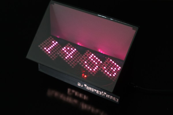
If you’ve never heard of Aerial Imaging by Retro-Reflection, or AIRR for short, you’re probably not the only one. It’s a technique developed by researchers at Utsunomiya University that uses beam splitters and retroreflective foil to create the illusion of an image floating freely in the air. Hackaday alum [Moritz v. Sivers] has been experimenting with the technique to make — what else — a clock, appropriately called the Floating Display Clock.
The most commonly available retroreflective films are typically used for things like street signs and high-visibility clothing, but also work perfectly fine for homebrew AIRR setups. [Moritz] tried several types and found that one called Oralite Superlens 3000 resulted in the best image quality. He combined it with a sheet of teleprompter glass and mounted both in their appropriate orientation in a black 3D printed enclosure.
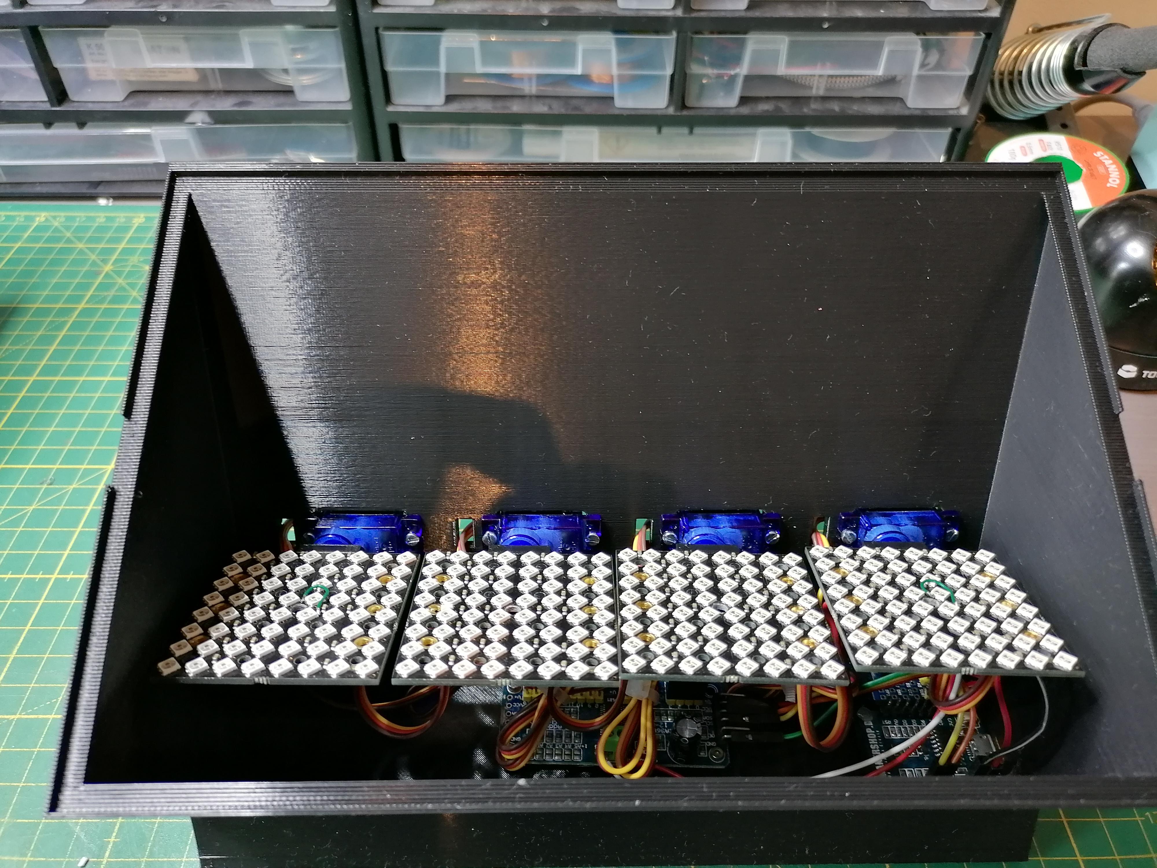
The projected image is generated by a set of 8×8 RGB LED displays, which are driven by a PCA9685 sixteen-channel servo driver board. A Wemos D1 Mini fetches the time from an NTP server and operates the display system, which includes not only the LED panels but also a set of servos that tilt each digit when it changes, giving the clock an added 3D effect that matches nicely with the odd illusion of digits floating in space.
We can imagine it’s pretty hard to capture the end result on video, and the demonstration embedded below probably doesn’t do it justice. But thanks to [Moritz]’s clear step-by-step instructions on his Instructables page, it shouldn’t be too hard to replicate his project and see for yourself what it looks like in real life.
Although this isn’t a hologram, it does look similar to the manydisplaytypes that are commonly called “holographic”. If you want to make actual holograms, that’s entirely possible, too.
[Koraks tinkers] was gifted a gargantuan photographic enlarger, a Durst Laborator 138 s, which is a unit designed specifically for black and white usage only. This was not good enough for [Koraks] so down the rabbit hole of conversion to colour we go! The moral of the story is this: if you can’t find it, build it. The hacker mentality. After wasting time and effort trying to source a period colour head for the thing, [Koraks] did the decent thing and converted what was already in front of them.
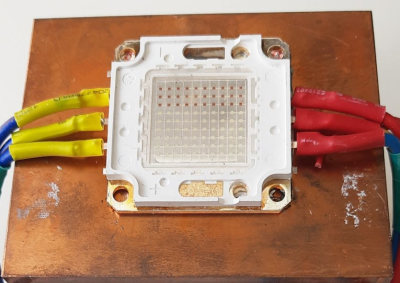
A hacked Chinese-sourced COB array. This is no use.
Now, if you’re thinking this process is simply a matter of ripping out the tungsten bulb and sticking a high-power RGB array in there, then you’re going to be disappointed! You see, colour photography of the era — specifically the RA4 process in this case — requires careful colour calibration and is heavily biased towards the red end of the visible spectrum, due to the colour curve of those tungsten bulbs we touched upon earlier.
Attempt 2: With a heavy bias towards the red end of the spectrum
The first attempt at using an off-the-shelf COB array was a bust — it simply wasn’t bright enough once the light had passed through the diffuser plate, and the light path losses were too high to expose the RA4 paper sufficiently, especially at the red end of the spectrum. Quite simply this is due to the reduced energy of red photons (compared to blue) making the desired chemical reaction rate too low. The solution is more power.
Another issue that quickly raised itself was that 8-bits of PWM control of the RGB components was inadequate since the ratio of blue to red required was so skewed, that only a few effective bits of blue channel control were usable, and that was far too granular to get the necessary accuracy.
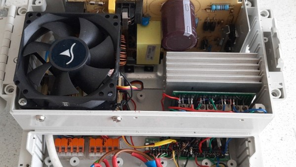
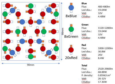
[Koraks’] approach was to custom build an LED array with twenty red 3W LEDs and eight each of the green and blue devices. 12-bits of PWM resolution was delivered via a PCA9685 PWM controller, that also handily controlled the cooling fans. The whole thing was hooked up to an Arduino Nano, with an MCP23016 expander board performing the duty of interfacing the rotary encoders and trigger footswitch. In fact, several iterations of the LED array have been constructed and this four-part blog series (Part1, Part2, Part3, Part4) lays out the whole story in all its gory detail for your entertainment. Enjoy!
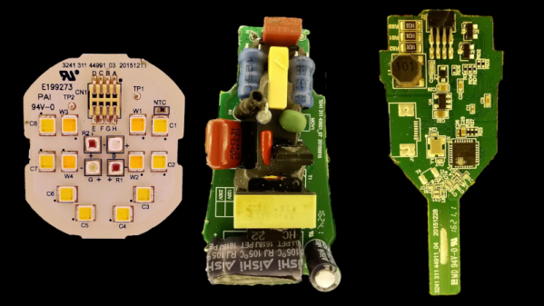
What do you do with a Hue smart lightbulb? Well, if you are [Chris Greening], you take it apart and get hacking. If you ever wondered what’s inside, the teardown is pretty good, and you can also watch the video below. The potting compound, however, makes a mess.
Once you get the potting undone, there are three PCBs: an LED carrier, a power supply, and a logic board. The arrangement of the LEDs is a bit confusing, but [Chris] explains it along with providing schematics for all of the boards.
Even if surface-mount skills aren’t in your repertoire, chances are pretty good that most of us are at least familiar with SMD stencils. These paper-thin laser-cut steel sheets are a handy way to apply a schmear of solder paste to the pads of a PCB before component placement and reflowing. But are stencils good for anything else?
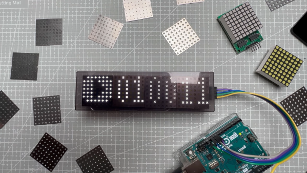
It turns out they are, if you’ve got some plain old 8×8 LED matrix displays you want to jazz up a bit. In this case, [upir]’s displays were of the square pixel type, but this trick would work just as well for a matrix with circular elements. Most of the video below is a master class in Adobe Illustrator, which [upir] used to generate the artwork for his stencils. There are a lot of great tips here that make creating one simple shape and copying it over the whole array with the proper spacing a lot easier. He also details panelizing multiple stencils, as well as the workflow from Illustrator to manufacturing.
When lined up properly over the face of the LED matrix, the stencils have quite an effect. We really liked the narrow vertical bars, which make the LED display look a bit like a VFD. And just because [upir] chose to use the same simple shape over all the LEDs in a matrix doesn’t mean that there aren’t other options. We can see how you might use the same technique to create different icons or even alphanumeric characters to create custom LED displays. The possibilities are pretty much limited to your imagination.