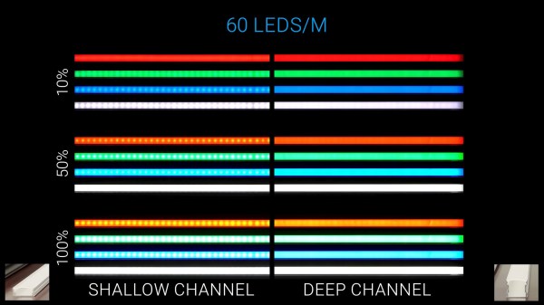
We all want a nice and shiny LED strip that doesn’t actually look like it consists of individual LEDs – a bar of uniform light is just that much more attractive. There’s all kinds of diffusion options available out there, but they can be confusing – sometimes you’d just like to know, which one is better? If there’s one thing that could easily settle this, it’s a practical test, and that’s what [The Hook Up] has devised for us to learn from.
First off, he talks about LED strips available – between 30, 60 and 144 LED per meter variations, the latter is going to be easier to diffuse than the former. From there, there’s a few different kinds of diffuser covers and aluminum profiles you can get, and [The Hook Up] pairs them in combinations, filming them from a distance and giving us concise visuals of how each combination works at different duty cycles, as well as making brightness measurements every now and then to evaluate losses of different diffuser layers. He proposes a simple rule – when picking a diffuser, distance between the LEDs and the diffuser has to be larger than the between-LED distance, and experiments confirm that. In the end, one of the takeaways is that the differences between 60LED/m and 144LED/m strips are not significant enough that they can’t be compensated for with a decent diffuser.
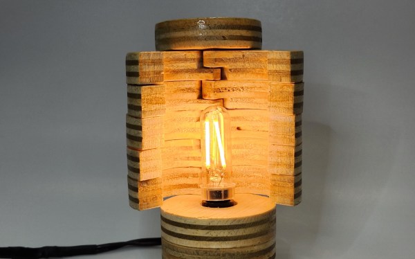
There’s something about light fixtures that attracts makers like moths to a flame. [danthemakerman] wanted something with a more configurable light output and built this Sculptural and Customizable Plywood Lamp.
In his detailed build log, [danthemakerman] describes how he wanted something “sort of like an analog dimmable light.” By using a stack of split plywood donuts hinged on a brass rod, he can vary the output and shape of the lamp. These shutters allow the lamp to go from bright to nightlight without using any electrical dimming components.
The plywood was rough cut on a bandsaw before being turned on a lathe. The light cover sections were then hollowed out with a Forstner bit and split in half. The tricky bit is the overlap of the cut on the hinge side of the shutters. Cutting the piece exactly in half would’ve required a lot more hardware to make this lamp work than what was achieved by patient woodworking.
Being visible to motorists is a constant concern for cyclists, but we doubt [The Q] will have this problem with his RGB LED illuminated tires made from glue sticks.
The project started with a set of 3D-printed tire molds that bolt to the standard wheels. A bot of melted glue sticks is poured into the mold, allowed to cool, and the mold sections are removed with the help of a heat gun after cooling. We doubt the weight and hardness make the tires particularly practical, but you can’t make normal tires glow from the inside.
The idea to illuminate the tires probably came after molding, because they had to be cut off to fit the LEDs. [The Q] built a simple hot wire jig with a piece of nichrome wire between two screws and used it to cut a few millimeters from the inside of the tire and fit a sleeved RGB LED strip in the wheel. Power come from a set of three 18650 batteries housed with a wireless controller in a 3D printed hub-mounted enclosure.
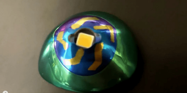
Cyberpunk is full of characters with cool body mods, and [bsmachinist] has made a prosthetic eye flashlight (TikTok) that is both useful and looks futuristic. [via Reddit]
[bsmachinist] has been machining titanium prosthetic eyes for over five years now, and this latest iteration, the Skull Lamp, has a high brightness LED that he says is great for reading books at night as well as any other task you might have for a headlamp. Battery life is reported as being 20 hours, and the device is switched by passing a magnet (Instagram) near the prosthetic.
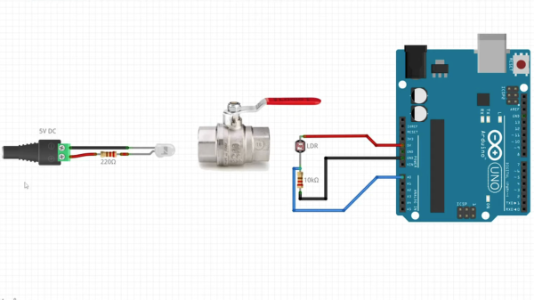
Input devices that can handle rough and tumble environments aren’t nearly as varied as their more fragile siblings. [Alastair Aitchison] has devised a brilliant way of detecting inputs from plumbing valves that opens up another option. (YouTube) [via Arduino Blog]
While [Aitchison] could’ve run the plumbing valves with water inside and detected flow, he decided the more elegant solution would be to use photosensors and an LED to simplify the system. This avoids the added cost of a pump and flow sensors as well as the questionable proposition of mixing electronics and water. By analyzing the change in light intensity as the valve closes or opens, you can take input for a range of values or set a threshold for an on/off condition.
[Aitchison] designed these for an escape room, but we can see them being great for museums, amusement parks, or even for (train) simulators. He says one of the main reasons he picked plumbing valves was for their aesthetics. Industrial switches and arcade buttons have their place, but certainly aren’t the best fit in some situations, especially if you’re going for a period feel. Plus, since the sensor itself doesn’t have any moving parts, these analog inputs will be easy to repair should anything happen to the valve itself.
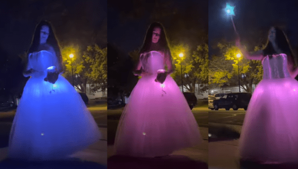
[Kellechu] went full parent beast mode by creating a prom dress for her daughter. This incredible build is a tour-de-force of DIY crafting, combining sewing, electronics, 3D printing and programming.
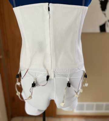
The dress skirt is made of tulle that allows for the LED strip underneath to diffuse through. The top bodice is made of fiber optic fabric sewn between the fabric form with the dangling fiber optic threads grouped into bundles. The dangling fiber optic bundles were then inserted and glued into “out caps” that forced the strands to sit next to a NeoPixel LED. A 20 NeoPixel “Dots Strand” strip was strung around the waist line, affixing 12 of the NeoPixels with an “out cap” to light up the fiber optic bodice. The remaining NeoPixels were outfitted with a diffuser cap and hung lower to light up the tulle skirt portion of the dress.
A wand was 3D printed and housed with an RFM69HCW Packet Radio M0 Feather, a NeoPixel LED color ring and a TCS34725 Flora color sensor powered by a 2.2 Ah 3.7 V LiPo battery. Another RFM69HCW Packet Radio M0 Feather was placed in the dress to be able to receive messages from the wand so that the sensed color could be transmitted and the LED strip could be updated with the sensed color. The dress portion was powered by a 10 Ah 3.7 V LiPo, with the battery and electronics fitting snugly into yoga bike shorts with side pockets.
[Kellechu]’s Instructable is full of details about the process and is worth checking out. For example, [Kellechu] goes into detail about the troubles and care taken when dealing with the different media, making sure to avoid ironing the fiber optics so as not to melt the lines and experimenting with different sewing needles to limit the amount of dead fibers as collateral damage from the sewing process.
Dresses with LEDs and other lights are a big hit, as can be seen from our feature on an LED wedding dress.
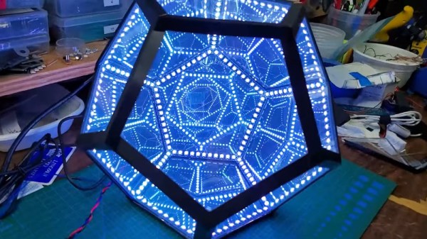
The infinity dodecahedron is one of those super eye-catching builds that many of us hardware hackers have on our ‘build one day’ project list. The very thought of actually doing it strikes a little fear into the heart of even the most intrepid maker, once you start to think about all the intricate little details and associated ways it could all go horribly wrong. Luckily for us, [Hari Wiguna] has documented his latest build as a long video build log, showing lots of neat tricks and highlighting many problems along the way. With the eventual goal of removing many of the issues that make such a build tricky, [Hari] hopes to make it practically easy. Let’s see how that turns out!
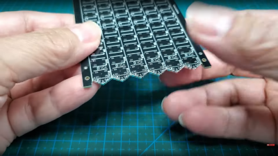
HASL-finished castellated (half hole) edge contacts make butt-jointing a breeze
A common route for such a build relies on appropriately shaped 3D printed frame parts, with some kind of clear plastic for the 12 faces, and LED strips stuck to the inside of each of the 30 edges. Whilst this works, [Hari] thought he could do a bit better, using butt-jointed PCBs as the frame material.
The PCBs handily double up as something to solder LEDs onto (because that’s what PCBs are mostly intended for!) as well as a way to pass power and data signals around the frame in a minimally visible way. As will become obvious from the lengthy discussion in the video, a few simple tricks here and there are needed to make this strategy work. With the recent proliferation of PCB modules using castellated edges for termination, the usual Chinese PCB fab services have all started offering very good value services for this feature. Once a PCB feature that was a specialized (read that as ‘expensive’) offering, it is now quite affordable on your average maker’s budget.
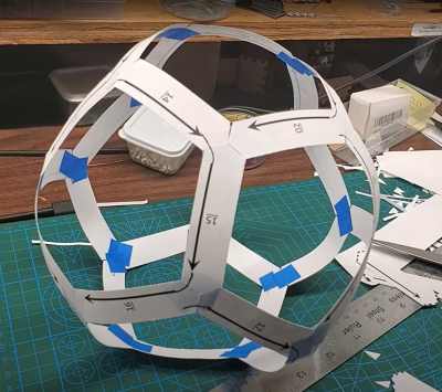
Data path planning? Just use paper and tape!
One immediate practical issue was how to pass the data connection around from edge to edge, given that there are three edges per vertex. The solution [Hari] came up with was simple, just duplicate the signals on each end of the PCB, so the data out signal can be tapped from either end, as required.
Even with 3D printed jigs to hold the PCBs at just the right angles, there’s still some wiggle and a little risk of edges not quite aligning, due to accumulated errors around the frame. It did come together in the end, with the expected spectacular visuals. We’re sure many of you will be waiting for [Hari] to release the next version of the design to the community, hopefully with even more of the ease-of-build issues resolved, because we want one even more now.
Naturally, this is by no means the first infinity platonic solid we’ve seen, here’s a smaller one for starters. If you remove the mirrors and LEDs, then you’re just left with a plain old dodecahedron, like this cool folding project.