You’ve probably had a company not support one of your devices as long as you’d like, whether it was a smart speaker or a phone, but what happens if you have a medical implant that is no longer supported? [Liam Drew] did a deep dive on what the failure of several neurotechnology startups means for the patients using their devices.
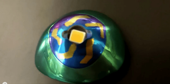
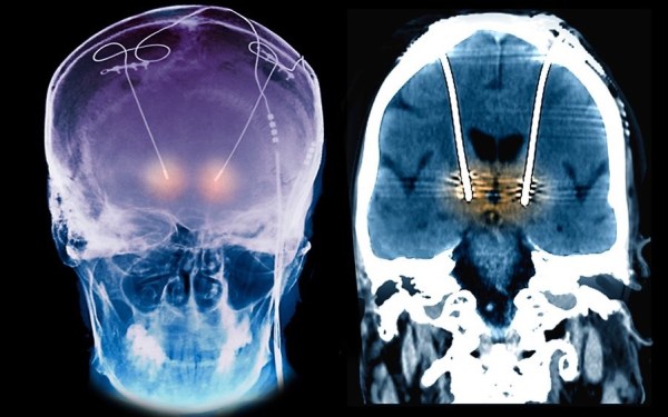
Recent advances in electronics and neurology have led to new treatments for neurological problems with implantable devices like the Autonomic Technologies (ATI) implant for managing cluster headaches. Now that the company has gone out of business, users are left on their own trying to hack the device to increase its lifespan or turning back to pharmaceuticals that don’t do the job as well as tapping directly into the nervous system. Since removing defunct implants is expensive (up to $40k!) and includes the usual list of risks for surgery, many patients have opted to keep their nonfunctional implants. Continue reading “What Happens When Implants Become Abandonware?”