ESP-01 Bridges The Gap Between IR And WiFi

[Emilio Ficara] dropped us a line recently about his efforts to drag his television and receiver kicking and screaming into the modern era. His TV is old enough that it needs an external tuner, which means it requires two separate remotes to properly channel surf. He wanted to simplify the situation, and figured that while he was at it he might as well make the whole thing controllable over WiFi.

To begin the project, [Emilio] had to capture the IR signals from the two remotes he wanted to emulate. He put together a quick little IR receiver out of parts he had in the junk bin which would connect up to his computer’s microphone port. He then used an open source IR protocol analyzer to capture the codes and decode them into hex values.

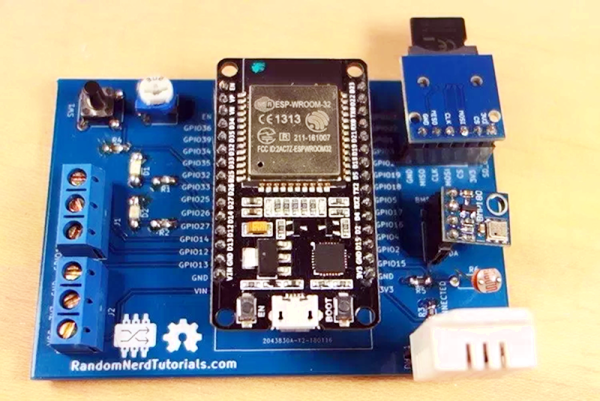
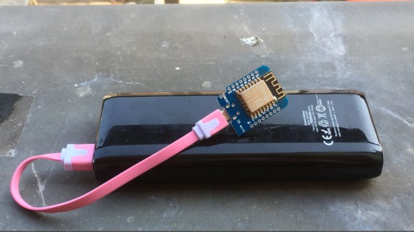
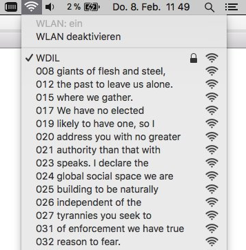
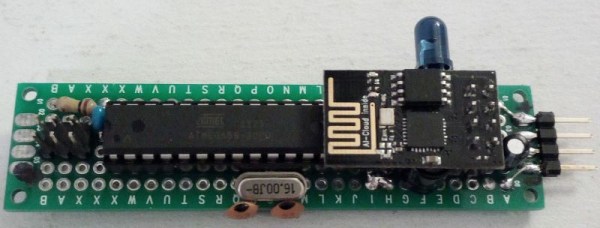
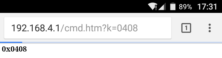
As a proof of concept he came up with a little device that combines an ESP-01 with an ATmega88. The ESP-01 runs a minimal web server that receives hex codes as URL query strings. These hex codes are then interpreted by the ATmega88 and sent out over the IR LED. [Emilio] notes that driving the IR LED directly off of the ATmega pin results in fairly low range of around one meter, but that’s good enough for his purposes. If you want to drive the IR LED with more power, you’ll need to add a transistor to do the switching.

Passing the hex code 0x0408 to turn off the TV

Now that he can decode the signals from his original remotes and transmit them over WiFi via his bridge device, he has all the groundwork he needs to come up with a streamlined home entertainment controller. A native application for his smartphone or perhaps a minimal web interface is the last piece of the puzzle.

This project reminds us of a similar attempt at controlling legacy IR devices from a smartphone via Bluetooth. If you’re looking for more information about wrangling IR signals from your microcontroller, this primer from 2013 is still a great look at the subject.

Building An Arduino Smart IC Tester For $25

There’s no question that you can get a lot done with the classic multimeter; it’s arguably the single most capable tool on your bench. But the farther down the rabbit hole of hacking and reverse engineering you go, the more extravagant your testing and diagnostic gear tends to get. For some of us that’s just an annoying reality of the game. For others it’s an excuse to buy, and maybe even build, some highly specialized equipment. We’ll give you one guess as to which group we fall into here at Hackaday.

[Akshay Baweja] is clearly a member of the second group. He’s recently published a guide on building a very slick intelligent Integrated Circuit tester with a total cost of under $25 USD. Whether you’re trying to identify an unknown chip or verifying your latest parts off the slow-boat from China actually work before installing them in your finished product, this $25 tool could end up saving you a lot of time and aggravation.

[Akshay] walks readers through the components and assembly of his IC tester, which takes the form of a Shield for the Arduino Mega 2560. The custom PCB he designed and had manufactured holds the 20 Pin ZIF Socket as well as the 2.4 inch TFT touch screen. The screen features an integrated micro SD slot which is important as you need the SD card to hold the chip database.

With an IC to test inserted into the ZIF socket, the user can have the tester attempt to automatically ID the chip or can manually enter in a part number to lookup. The source code for the Arduino as well as the chip ID database is up on GitHub for anyone looking to add some more hardware to the device’s testing repertoire.

The importance of good test equipment simply cannot be overstated. Between highly specialized gear like this IC tester to classic instruments such as the oscilloscope, your bench is going to be full of weird and wonderful pieces of equipment before too long.

Continue reading “Building An Arduino Smart IC Tester For $25”

Getting Started With STM8

There are so many different CPUs today and often the hardest thing about using any of them is getting started and gathering the right software tools. If you’ve ever eyed up the very inexpensive STM8 processor, you’ll want to check out [Shane Burrell’s] video (see below) about how to get started with the STM8.

The STM8 isn’t a 32-bit processor — you could probably guess that from the name. [Shane] uses SDCC (small device C compiler) to target the little chip. He also shows how he manages a fairly substantial piece of code and how he controls the build process.

Continue reading “Getting Started With STM8”

Flood Damaged 386 Gets A Modern Rebuild

Until a flood claimed its life, the 386 tower [Tylinol] found on the side of the road served him well as a DOS gaming rig. In the aftermath of the flood, the machine was left with ruined internals and a rusted case; it ended up being tossed in storage where it was slowly rotting away. But a recent idea got him to drag this old dinosaur back out into the light of day and give it a new lease on life with some modern gear.

For our viewing pleasure [Tylinol] documented the restoration of the computer, dubbed SErEndIPITy, from start to finish. The rebuild starts with tearing the machine down to the steel frame and sanding all the rust off. Luckily it looks like no structural damage was done, and a coat of engine enamel got the frame looking more or less like new. The original motherboard mounting solution wouldn’t work for his modern board, so he ended up riveting a piece of sheet metal in and drilling new holes for standoffs to thread into.

A nice element of this rebuild is that [Tylinol] didn’t want to drastically change the outward appearance of the machine. The customary yellowed plastic was left alone, and wherever possible the original hardware was reused. Rather than blow a hole in the case, he took his Dremel to the decorative ribbed design of the front panel and turned it into a stock-looking vent.

The real star of this rebuild is the LED CPU “Speed” display on the front of the case. In its original form, this was a fake display that simply cycled through predefined digits when you pressed the “Turbo” button on the front panel. By grounding them one at a time, [Tylinol] figured out which lines on the PCB controlled each segment of the display and wired it up to a Teensy 3.5. He was then able to write a C# plugin for CoreTemp to display the temperature.

The rebuilt machine is packing an i5-6500 processor, GTX 970 video card, and 8 GB of DDR4 RAM. Not exactly a speed demon compared to some of the modern desktops out there, but it certainly beats the original hardware. Incidentally, so does the Teensy 3.5 controlling the front panel display. There’s a certain irony there…

Cramming modern hardware into the carcass of an outdated computer is nothing new, of course. But we especially like the builds that take the time to make it all look stock.

[via /r/DIY]

ESP32 Weather Station On A PCB

We see lots of ESP8266 projects, but considerably fewer for the ESP32. So this good-looking weather station on a PCB using an ESP32 caught our eye. The board has a few sockets for common weather gear, but with a little modification, it would be a great carrier for an ESP32. Since the PCB layout is available, you could change things around to suit you. You can see a video from [Rui Santos] about his project and its progress from breadboard to PCB in the video below.

Continue reading “ESP32 Weather Station On A PCB”

ESP8266 Broadcasts Memorial WiFi Spam

John Perry Barlow, founding member of the Electronic Frontier Foundation and Freedom of the Press Foundation, died on February 7th, 2018. To say that he left his mark on the Internet, and by extension modern culture, is something of an understatement. He may not be a household name, but between this activism (online and off), lectures, written work, and various entrepreneurial projects, his 70 years of life were surely not wasted. Barlow was once quoted as saying “I want to be a good ancestor”, and by pretty much any metric it would seem he made good on that goal.

To mark his passing, [Moritz Metz] came up with a rather unusual memorial. Using a bit of code on an ESP8266 board, he created a device that would broadcast out Barlow’s “A Declaration of the Independence of Cyberspaceline-by-line in the form of 228 WiFi SSIDs. Perhaps not the most effective way to get Barlow’s words out to the people, but we’ll give him extra points for style.

The code itself is based on FakeBeaconESP8266, which as the name implies, allows the user to create fake WiFi networks. to broadcast the manifesto of your choosing, you need only add in the appropriate sendBeacon() lines at the bottom of the code. It would appear that prefixing each line with a number is required to make devices scanning for networks show the lines of text in proper sequence. At least on the devices demoed, anyway.

Just to be clear: you should definitely not do this. Jamming up the local environment with a bunch of fake networks is a pretty terrible idea. But as a memorial for a man who occasionally claimed to be an anarchist, you could do worse. Plus we have to admit “Giants of Flesh and Steel” is an awesome name for a network.

Continue reading “ESP8266 Broadcasts Memorial WiFi Spam”

Count Your Fans With This Stylish ESP8266 Display

Continuous self-affirmation is a vital component to the modern lifestyle. Of course you know the world loves you, but exactly how much do they love you? Checking your phone every few minutes to see if you’ve gained any followers is gauche, and perhaps more to the point, doesn’t let you show off when you’ve got visitors over. In the modern era, the up-and-coming social media star needs a stylish way to display just how popular they are for the world to see.

That’s the idea behind this very slick social media counter created by [Becky Stern]. Built into a standard shadow box frame and using LED displays glowing through a printed piece of paper, the finished product looks more like modern art than the usual hacker fare.

The counter is powered by a NodeMCU, but you could drop in your favorite variant of the ESP8266 and things would work more or less the same. For the displays, [Becky] is using four Adafruit 7-Segment LED modules, which are easily controlled via I2C which keeps the wiring to a minimum.

It’s interesting to note that since her follower count on Twitter has already hit five digits, two of the display modules are used next to each other for that particular service. Her Instructables and Instagram counters only have one display each however, limiting her counts on those services to 9,999 each. There’s probably something to be learned here in terms of the relative follower counts you can expect on the different social networks if you’re targeting your content to the hacker and maker crowd, but we’ll leave the analysis to those with a better handle on such matters.

Hardware aside, [Becky] spends a lot of time in the video talking about the code she’s come up with to pull her stats from the various services and push them out to the LED displays at a regular interval. It’s nice to see so much attention and explanation given to the software side of a project like this, as more often than not you’re left to your own to figure out what the source code is doing.

This project is quite similar to the YouTube Play Button hack we covered a few months back, but the addition of multiple social networks in one device is a nice improvement over the basic concept.

Continue reading “Count Your Fans With This Stylish ESP8266 Display”