One of the most useful tools in the hardware hackers toolbox is a USB to serial adapter. With this, you can flash new firmware to routers, and ply the vast binary seas of embedded hardware. The common form of the USB to Serial adapter is an FTDI breakout board. This requires drivers, though, and there is actually a simpler – and wireless – solution: the ESP8266 WiFi module.
Despite being the best little IoT device on the block, the ESP8266 was originally designed to be a USB to WiFi adapter. In our haste to build WiFi throwies, WiFi blinkies, and freaking WiFi server farms, we seem to have forgotten that there’s still a use for a device that turns a 3.3V TTL into a WiFi connection. It’s the perfect device for reflashing a cheap WiFI router with new firmware, or just providing you with wireless serial connections to go along with your wireless Internet.
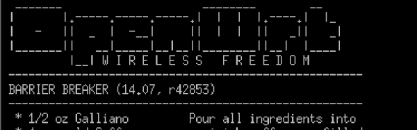
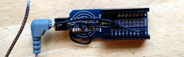
This project uses jeelabs’ ESP-link firmware for the ESP8266. It’s a simple bridge between WiFi and serial, and can function as an AVR programmer in a pinch. The web interface for this firmware is very nice, but you really don’t need it; the entire purpose of this firmware is to be even more transparent than an FTDI USB to serial adapter. For the next time you’re flashing a router with OpenWRT, don’t bother digging out the USB adapter; an ESP is all you need.

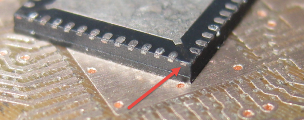
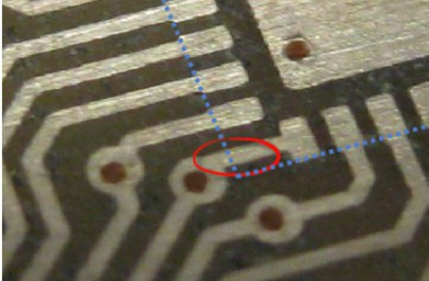 The PCB layout just happens to have a trace exiting right under this conductor. The two aren’t touching, but without solder mask, a bit of melted metal was able to mind the gap and connect the two conductors. [Eric] notes that although the non-pad isn’t documented, it’s easy to prove that it is connected to ground and was effectively pulling down the signal on that trace.