FPGA Snake Game Uses No VHDL At All

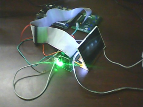
We’re really not supposed to start a feature like this; but this hack is awesome. It’s a game of Snake implemented by an FPGA dev board. It uses a 16×16 LED matrix as the display and an SNES controller for input. So far it sounds like a very normal version of the game. But as you start to hear how it works in the presentation after the break you fall in love with what’s going on here.

First of all, it’s not written in VHDL — the predominant programming language for FPGAs. Instead, [Darrell] used the schematic-only approach to build the logic. Okay, that’s starting to get more interesting. As he continues to explain the circuit we get to see how the control input works (pretty simple since the SNES controller uses a parallel-to-serial shift register) and how the display is multiplexed. But the actual game logic is where things really take off. Each pixel in the display has its own individual logic circuit. Basically every cell is its own processor which reacts both to what is passed into it, as well as to a random seed. That seed system is called the ‘bucket brigade’ and passes a chance to spawn a piece of food from one cell to the next. All of this together makes for one simple game that is eloquently executed. Continue reading “FPGA Snake Game Uses No VHDL At All”

Ball-in-maze Game Shows Creativity And Classic 8-bit Sound

[M. Eric Carr] built this a long time ago as his Senior Project for EET480. It’s an electronic version of the ball-in-maze game. We’ve embedded this video after the break for your convenience.

The game has just one input; an accelerometer. If you’re having trouble visualizing the game, it works the same as this Android-based version, but replaces the physical maze and marble with a virtual maze on the graphic LCD screen. This has huge implications. Instead of just recreating the maze on the screen, [Eric] designed a multi-screen world, complete with warp blocks, which adds difficulty to  finding a solution. It also means that multiple different mazes can be played if you get tired of playing the same level.

This game also features music. A separate PIC microcontroller uses PWM to push out the 8-bit sound heard in the video. From the YouTube comments we learned that [Eric] didn’t write the music himself, but we still appreciate the playback quality he achieves with his hardware.

Continue reading “Ball-in-maze Game Shows Creativity And Classic 8-bit Sound”

Commandeer X10-based Home Automation With Your Favorite Microcontroller

X10 has been around for a long time. It’s the brand name for a set of wireless modules used to switch electrical devices in the home. There’s all kinds of different units (bulb sockets, electrical outlets and plug pass-throughs, etc.) and they’re mass-produced which makes them really inexpensive. Whether you already have some X10 controlled devices or just plan to add them later, we think you’ll find [Jeff Ledger’s] post on controlling the system with a Propeller chip interesting. The technique is not Propeller specific and will be simple to port to your microcontroller of choice.

[Jeff] got his hands on an X10 Firecracker. This provides a DB-9 serial connection meant to be used for computer control. But the interface is so simple all you need is two I/O pins feeding the level converter circuit seen above. You can get the TC4427 for less than a dollar, and the Firecrcker module for as little as $6. Since [Jeff] has already covered adding Ethernet via a ENC28J60 he goes on to detail a web-server that lets him switch his devices, all served from the Propeller chip.

Here’s a different ENC28J60 Ethernet tutorial for those interested in webpages from microcontrollers. And then there’s also a ZigBee home automation project if you’re not warming up to the idea of using X10 modules.

The EMGRobotics Robot Control Board

There are many microcontrollers available to make robots with, but few that are built with the exact features that you would need to construct one. Meet the [EMGRobotics  MSP430G2553] robot controller board.

At $15 without the CPU or $17 with a [MSP430G2553] already plugged into the socket, this control board may make some Arduino enthusiasts take note for their next project.  Besides a very attractive price (you’ll have to go to the home page to make a purchase), this board ships with a built in IR range sensor and accommodations to drive up to four hobby servo motors. If this isn’t enough for you, two 3 volt DC motors can be soldered directly to connections on the board and controlled independently and in either direction. In other words you don’t have to muck about with trying to build your own H-bridge circuit, it’s all taken care of for you!

The article shows it controlling a Hexbug spider. [EMGRobotics] has actually done something similar (and well-documented) before with this platform, so be sure to check out the post about hacking the Hexbug iteslf!

$3 Adds Sweet Tunes To Your Project

It’s a fun time to design your own MP3 player, lovingly adding in features to a meticulously crafted user interface. But sometimes you just want a quick and cheap way to add music to a project. [Jeff Ledger] will show you how to do just that using some knock-off hardware from overseas. Instead of a proper breakout board — which can cost a bundle — he used a generic MP3 player acquired for $3 from an eBay seller.

Cracking open the case you’ll see that you actually get a lot for your triad of Washingtons. We know, it may be of questionable quality (see this feature about cheap PSU problems) but we’re not building mission critical hardware now are we? Inside is a rechargeable Lithium battery for use with another project, and a chip-on-board device with attached SD card slot, audio jack, and USB port. The battery inputs are used to solder the MP3 pcb to the power rails on your project. To control the playback, just make connections to the button pads as [Jeff] describes in his post. It sounds like this will work with any MP3 player which runs at either 3.3V or 5V.

Python Maps Mouse Movements On An LED Matrix

[Vinod Stanur] is working with a mouse input and a microcontroller driven LED matrix. The mouse cursor is tracked inside of a window by Python and the resulting coordinates on the LED grid are illuminated. He calls it an LED matrix “Paint Toy” because one of the features he’s included lets the user create pixel art like in MS Paint.

The 10×8 grid of lights is controlled by a PIC 16F877A. This display orientation is perfect for the 8-bit controller, which uses an array of ten bytes to keep track of the pixel data. A computer running his Python application (which uses the Pygame module to track the mouse movements) communicates with the display board via an RF connection. Five bytes plus a stop character make up the communication packet. The first two bytes contain the coordinates of the cursor, the other three bytes contain mouse button status.

As you can see in the demo after the break, the system is very responsive. The mouse can be moved quickly without latency issues, and if the cursor leaves the tracking window it gets picked up right away when it re-enters.

Continue reading “Python Maps Mouse Movements On An LED Matrix”

Tool Box Light Dimmer Helps Out A Friend, Offers Up Design Tips

toolbox-lighting

[miceuz] has a friend that works as a theatre technician, and in the course of his job he often needs to jigger with various stage components while shows are in progress. As you can imagine, the lighting situation is far from ideal, so he asked [miceuz] to build him an adjustable lighting solution for his tool box.

The circuit itself is relatively straightforward, using an ATMega88 to provide the PWM required for dimming and color control. Input is taken from three different sources, a rotary encoder for color selection, a pot for brightness control, and a button to turn the light strip on and off.

[miceuz] says that while project came together pretty easily, it still presented some issues along the way which provide some useful design reminders for beginners (and some veterans) alike.

First and foremost: debounce, debounce, debounce. [miceuz] forgot this mantra and made a mad dash to add capacitors to his design after etching the PCB to ensure that his inputs were not bouncing all over the place. He also noted that one should always be sure to read the ADCL before the ADCH register when decoding ADC data. His final observation is that using thick traces is the best policy whenever possible – he ran into a lot of issues with traces detaching during assembly, which he had to rework with wire and solder.

In the end, his friend was happy with the result, and [miceuz] is a better hacker for having worked through his issues. What sorts of important/useful lessons have you learned through the course of your projects? Be sure to share them with us in the comments.