Build A Standalone BASIC Interpreter

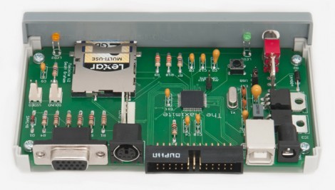
Here’s a photo of the circuit board for the Maximite, a BASIC interpreter that [Geoff] built. The design idea was sparked when he was exploring the possibilities of the PIC32 family of chips. [Geoff] wanted to write about the hardware for a magazine article but needed an actual product to really show it off.

The design can utilize one of two microprocessors, a PIC 32MX795F512H or 32MX695F512H. The 32-bit chip has more than enough power to emulate BASIC, and even allows for floating point calculations. It’s VGA compatible and has a jack for a standard PS/2 keyboard, which makes it a standalone device. You can store programs on an SD card, or it can be interfaced with a computer via the USB-B port that you see next to the power jack. The microprocessor is a surface mount chip, but the rest of the components are through-hole, making this an easy kit to assemble. But if you’re not afraid to etch your own 2-layered PCBs there is board artwork available in [Geoff’s] download package.

[Thanks Bill]
Keypad Uses A PIC’s Built In Capacitance Functionality

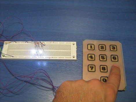
[Giorgos Lazaridis’] most recent project was to build a capacitive touch pad. Since he’s using a PIC 16F1937 it will be relatively easy. That’s because it has a 16 channel capacitance sensing module built right in. But there are still some design considerations that make the development a bit touching.

This isn’t the first time he’s worked with capacitance sensing. Through past experience he has found that it is very important to position the microcontroller as close to the button pads as possible. Because of this, the chip is soldered on the back of the PCB used for the keypad itself. Because he’s hand soldering vias, he also used some foam tape to raise the button pads just a bit. This way they will be flush with the acrylic overlay, which cannot sit flat on the board due the via solder joints.

Check out the video after the break to hear [Giorgos] walk us through the project.

Continue reading “Keypad Uses A PIC’s Built In Capacitance Functionality” →

Beginner Concepts: Using A Low-pass Filter To Smooth PWM Output

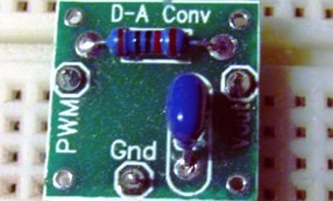
Microcontrollers are digital devices at heart. They can do fancy things like convert analog signals into a digital value but going the other direction is a bit tougher. Pulse-Width Modulation is used to approximate an analog output but what you’re actually doing is turning the operating voltage on and off very quickly to achieve an average value somewhere in between. This is the method most commonly used to dim an LED. But generating a smooth voltage in this way takes just a few more parts.

[Scott Daniels] spent some time discussing the process of smoothing a PWM output by using a low pass filter. This is a compilation of digital and analog circuitry to produce a smoother signal than PWM can achieve on its own. As you can see above, the low pass filter is made up of one resistor and one capacitor. The theory is not hard to understand, and with [Scott’s] help you’ll become much more comfortable with choosing the component values for your own filters. His examples center around an Arduino using the analogWrite() function but the techniques can be applied universally.

ChipKIT Sketch: Mini Polyphonic Sampling Synth

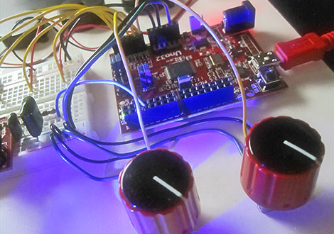
In our hands-on review of the Digilent chipKIT Uno32, we posed the question of what the lasting appeal might be for a 32-bit Arduino work-alike. We felt it needed some novel applications exploiting its special features…not just the same old Arduino sketches with MOAR BITS. After the fractal demo, we’ve hit upon something unique and fun…

Continue reading “ChipKIT Sketch: Mini Polyphonic Sampling Synth” →

Working With I2C Port Expanders

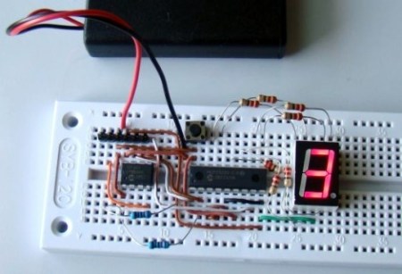
There are times when you don’t need much processing power for your project but you do need a lot of I/O pins. It often doesn’t make economic sense to choose a larger microcontroller just to get extra pins so the answer is to use a port expander chip. [Raendra] posted a guide for using one of these chips, it’s a Microchip MCP23008 chip that uses the I2C protocol for communications.

You are probably already familiar with using shift registers like the 595 series for port expansion. There can be benefits to using an I2C device instead. One of them comes when using multiple port expander chips. With cascading shift registers you must always shift in the data for the entire chain of chips. But I2C devices are individually addressable, so you only need to push data over the I2C bus for the chips that need to be changed, the others will remain unaffected. It is especially easy to use these if you already have another I2C device in your project design as the addition only requires the connection of the SDA and SCL lines. Keep them in mind for future undertakings.

DIY Digital Bench Power Supply

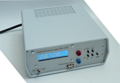
[Guido Socher] built himself a great little bench power supply that’s able to put out 30 Volts at 2 Amps.

Instead of taking the easy way out by putting a few taps on an ATX power supply, this project was built around a generic 24 Volt laptop power brick. An ATmega8 generates a PWM signal that is sent though a low-pass filter, allowing everything to be very precisely controlled. This DC signal is then sent through a BD245 power transistor to bring everything up to the desired output. [Guido Socher] included a USB port for computer control of everything, and the final project is something we’d be happy to have on our bench.

We’ve seen a few computer power supplies converted into a bench power source, but we’re impressed with [Guido Socher]’s build log. It’s not often we see a hack that goes over the theory of operation, and the end product is very nice (and functional) too.

Washing Machine Mechanical Timer Replaced With Microcontroller

After the electromechanical timer on [Paul Canello’s] washing machine broke for the third time he decided he needed to stop repairing it and find a more permanent fix. He decided to build his own microcontroller-based system for washing his clothes (translated). Caution: The image links on [Paul’s] page seem to be broken and will unleash a never-ending storm of empty pop-up windows if you click on them. We’ve embedded all of the images after the break to save you some hassle.

The controller on a washing machine is nothing more than a mechanical alarm clock. It starts the cycle, then moves through various modes based on the passage of time. [Paul] started his hack by observing how long the delay between cycles was meant to be, and recording which parts of the machine were switched on and off at each stage.

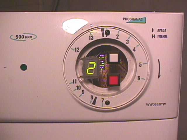
It turns out that when the mechanical knob is turned, it reroutes how water flows through the detergent chamber. Since that knob won’t be in the new system [Paul] came up with a way for the microcontroller to handle this by using a servo motor. The rest of the control involves relays to control the motor, and solenoid valves for the water. There are also pressure switches that give feedback for the level of the water in the machine. A PIC 16F872 serves as the new controller, with the help of a 7 segment display, a buzzer, and a pair of buttons as the user interface.

This is an older project, but after reading about the Arduino controlled dishwasher [Ramiro] sent us a link. Thanks! Continue reading “Washing Machine Mechanical Timer Replaced With Microcontroller” →