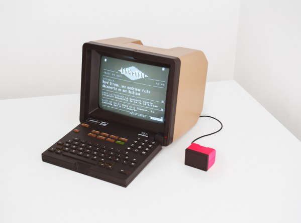
What’s That Scope Trace Saying? UPD And Wireshark

[Matt Keeter], like many of us, has a lot of network-connected devices and an oscilloscope. He decided he wanted to look into what was on the network. While most of us might reach for Wireshark, he started at the PCB level. In particular, he had — or, rather, had someone — solder an active differential probe soldered into an Ethernet switch. The scope attached is a Textronix, but it didn’t have the analyzer to read network data. However, he was able to capture 190+ MB of data and wrote a simple parser to analyze the network data pulled from the switch.

The point of probing is between a network switch and the PHY that expands one encoded channel into four physical connections using QSGMII (quad serial gigabit media-independent interface). As the name implies, this jams four SGMII channels onto one pair.

As is common in networking schemes, the 8-bit byte is encoded into a 10-bit code group to ensure enough bit transitions to recover the synchronous clock. The decoding software has to examine the stream to find framing characters and then synchronize to the transmitted clock.

What follows is a nice tour of the protocol and the Python code to decode it. It seems complex, but the code is fairly short and also executes quickly. The output? Pcap files that you can process with Wireshark. Overall, a great piece of analysis. He also points out there are other tools already available to do this kind of decoding, but what fun is that?

Wireshark can do a lot of different kinds of analysis, even if you aren’t usually capturing from a scope. You can even decrypt SSL if you know the right keys.

Stratum 1 Grandmaster Time Server On A Budget

[Jeff Geerling] has been following the various open source time projects for some time now, and is finally able to demonstrate a working and affordable solution for nanoseconds-accurate timekeeping in your local lab. The possibility of a low-cost time server came about with the introduction of the Raspberry Pi CM4 compute module back in Oct 2020, whose Broadcom network chip (BCM54210PE) supports PTP (Precision Time Protocol, IEEE-1588) 1PPS output and hardware-based time stamping. Despite the CM4 data sheet specifying PTP support, it wasn’t available in the kernel. An issue was raised in Feb last year, and Raspberry Pi kernel support was finally released this month.

[Jeff] demonstrates how easy it is to get two CM4 modules to synchronize to within a few tens of nanoseconds in the video below the break. That alone can be very useful on many projects. But if you want really stable and absolute time, you need a stratum 1 external source. These time servers, called grandmasters in PTP nomenclature, have traditionally been specialized pieces of kit costing tens of thousands of dollars, using precision oscillators for stability and RF signals from stratum 0 devices like navigation satellites or terrestrial broadcast stations to get absolute time. But as Lasse Johnsen, who worked on the kernel updates remarks in the video:

In 2022 these purpose-built grandmaster clocks from the traditional vendors are about as relevant as the appliance web servers like the Raq and Qube were back in 1998.

It is now possible to build your own low-cost stratum 1 time server in your lab from open source projects. Two examples shown in the video. The Open Time Server project’s Timecard uses a GNSS satellite receiver and a Microchip MAC-SA5X Rubidium oscillator. If that’s overkill for your projects or budget, the Time4Pi CM4 hat is about to be release for under $200. If accurate time keeping is your thing, the technology is now within reach of the average home lab. You can also add PTP to a non-CM4 Raspberry Pi — check out the Real-Time HAT that we covered last year.

Continue reading “Stratum 1 Grandmaster Time Server On A Budget”

Sorry, Your Internet Connection Is Slow

How fast is your Internet connection? The days of 56K modems are — thankfully — long gone for most of us. But before you get too smug with your gigabit fiber connection, have a look at what researchers from the Network Research Institute in Japan have accomplished. Using a standard diameter fiber, they’ve moved data at a rate of 1 petabit per second.

The standard fiber has four spatial channels in one cladding. Using wavelength division multiplexing, the researchers deployed a total of 801 channels with a bandwidth over 20 THz. The fiber distance was over 50 km, so this wasn’t just from one side of a lab to another. Well if you look at the pictures perhaps it was, but with big spools of fiber between the two lab benches. The project uses three distinct bands for data transmission with 335 channels in the S-band, 200 channels in the C-band, and 266 channels in the L-band.

To put this into perspective, a petabit — in theory — could carry a million gigabit Ethernet connections if you ignore overhead and other losses. But even if that’s off by a factor of 10 it is still impressive. We can’t imagine this will be in people’s homes anytime soon but it is easy to see the use for major backhaul networks that carry lots of traffic.

We are still amazed that we’ve gone from ALOHA to 2.5-gigabit connections. Although the Raspberry Pi can’t handle even a fraction of the bandwidth, you can fit it with a 10-gigabit network card.

Dissecting A T1 Line

When it comes to internet connections, here in 2022 so many of us have it easy. Our ISP provides us with a fibre, cable, or DSL line, and we just plug in and go. It’s become ubiquitous to the extent that many customers no longer use the analogue phone line that’s so often part of the package. But before there was easy access to DSL there were leased lines, and it’s one of these that [Old VCR] is dissecting. The line in question is a T1 connection good for 1.536 Mbit/s and installed at great cost in the days before his cable provider offered reliable service, but over a decade later is now surplus to requirements. The ISP didn’t ask for their router back, so what else to do but give it the hacking treatment?

In a lengthy blog post, he takes us through the details of what a T1 line is and how it’s installed using two copper lines, before diving into the router itself. It’s an obsolete Samsung device, and as he examined the chips he found not the MIPS or ARM processors we’d expect from domestic gear of the period, but a PowerPC SoC from Freescale. Connecting to the serial port reveals it as running SNOS, or Samsung Network Operating System from an SD card, and some experimentation finds a default password reset procedure through the bootloader commands. The rest of the piece is dedicated to exploring this OS.

There was a time before the advent of the Raspberry Pi and similar cheap Linux-capable boards, that hacking a router was the way to get a cheap embedded Linux system, but now it’s much more done to liberate a router from the clutches of manufacturer and telco. Still, it’s very much still part of the common fare here at Hackaday.

Easy Network Config For IoT Devices With RGBeacon

When you’re hooking up hardware to a network, it can sometimes be a pain to figure out what IP address the device has ended up with. [Bas Pijls] often saw this problem occurring in the classroom, and set about creating a simple method for small devices to communicate their IP address and other data with a minimum of fuss.

[Bas] specifically wanted a way to do this without adding a display to the hardware, as this would add a lot of complexity and expense to simple IoT devices. Instead, RGBeacon was created, wherin a microcontroller flashes out network information with the aid of a single RGB WS2812B LED.

In fact, all three colors of the RGB LED are used to send information to a computer via a webcam. The red channel flashes out a clock signal, the green channel represents the beginning of a byte, and the blue channel flashes to indicate bits that are high. With a little signal processing, a computer running a Javascript app in a web browser can receive information from a microcontroller flashing its LEDs via a webcam.

It’s a neat hack that should make setting up devices in [Bas]’s classes much easier. It needn’t be limited to network info, either; the code could be repurposed to let a microcontroller flash out other messages, too. It’s not dissimilar from the old Timex Datalink watches which used monitor flashes to communicate!

Meet The RouterPi, A Compute Module 4 Based GbE Router

[Zak Kemble] likes to build things, and for several years has been pining over various Raspberry Pi products with an eye on putting them into service as a router. Sadly, none of them so far provided what he was looking for with regard to the raw throughput of the Gigabit Ethernet ports. His hopes were renewed when the Compute Module 4 came on scene, and [Zak] set out to turn the CM4 module into a full Gigabit Ethernet router. The project is documented on his excellent website, and sources are provided via a link to GitHub.

A view underneath shows off the RTC, power supply, and more.

Of course the Compute Module 4 is just a module- it’s designed to be built into another product, and this is one of the many things differentiating it from a traditional Raspberry Pi. [Zak] designed a simple two layer PCB that breaks out the CM4’s main features. But a router with just one Ethernet port, even if it’s GbE, isn’t really a router. [Zak] added a Realtek RTL8111HS GbE controller to the PCIe bus, ensuring that he’d be able to get the full bandwidth of the device.

The list of fancy addons is fairly long, but it includes such neat hacks as the ability to power other network devices by passing through the 12 V power supply, having a poweroff button and a hard reset button, and even including an environmental sensor (although he doesn’t go into why… but why not, right?).

Testing the RouterPi uncovered some performance bottlenecks that were solved with some clever tweaks to the software that assigned different ports an tasks to different CPU cores. Overall, it’s a great looking device and has been successfully server [Zak] as a router, a DNS resolver, and more- what more can you ask for from an experimental project?

This CM4 based project is a wonderful contrast to Cisco’s first network product, which in itself was innovative at the the time, but definitely didn’t have Gigabit Ethernet. Thanks to [Adrian] for the tip!

Wireshark HTTPS Decryption

If you’ve done any network programming or hacking, you’ve probably used Wireshark. If you haven’t, then you certainly should. Wireshark lets you capture and analyze data flowing over a network — think of it as an oscilloscope for network traffic. However, by design, HTTPS traffic doesn’t give up its contents. Sure, you can see the packets, but you can’t read them — that’s one of the purposes of HTTPS is to prevent people snooping on your traffic from reading your data. But what if you are debugging your own code? You know what is supposed to be in the packet, but things aren’t working for some reason. Can you decrypt your own HTTPS traffic? The answer is yes and [rl1987] shows you how.

Don’t worry, though. This doesn’t let you snoop on anyone’s information. You need to share a key between the target browser or application and Wireshark. The method depends on the target applications like a browser writing out information about its keys. Chrome, Firefox, and other software that uses NSS/OpenSSL libraries will recognize an SSLKEYLOGFILE environment variable that will cause them to produce the correct output to a file you specify.

How you set this depends on your operating system, and that’s the bulk of the post is describing how to get the environment variable set on different operating systems. Wireshark understands the file created, so if you point it to the same file you are in business.

Of course, this also lets you creep on data the browser and plugins are sending which could be a good thing if you want to know what Google, Apple, or whoever is sending back to their home base using encrypted traffic.

Wireshark and helpers can do lots of things, even Bluetooth. If you just need to replay network data and not necessarily analyze it, you can do that, too.