While most people may think that a keyboard is just a board with keys, those who read Hackaday will no doubt know that there’s an infinite variety of beautiful designs to suit any use case. [Peng Zhihui] is the latest to impress us with an excellent custom keyboard that packs several unusual features (video in Chinese, with English subtitles, embedded below). What started out as a simple lockdown project turned into what [Zhihui] imagines to be the ultimate keyboard for his daily tasks. At first glance it might look like just another custom keyboard with mechanical switches, but when you look inside you’ll find it full of clever design tricks and neat features.
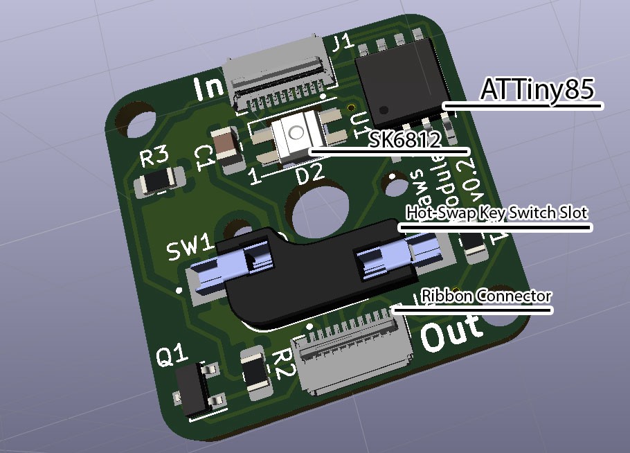
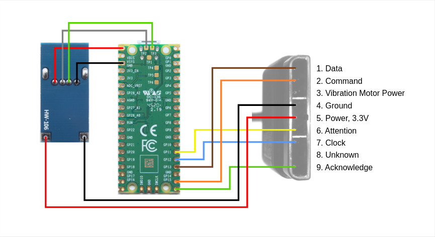
When he started on the design of the main key area, [Zhihui] could have used any of the open-source keyboard frameworks. Instead, he decided to do everything himself in order to obtain maximum performance and configurability. This went all the way down to the readout circuitry: rather than wiring the switches in a matrix, as most keyboards do, he used a set of shift registers. This enables the main ARM controller to read out every key separately, eliminating ghosting and allowing any number of keys to be pressed simultaneously. The shift registers are driven by a 4 MHz SPI clock, which means that a full scan of all keys takes just 40 microseconds.
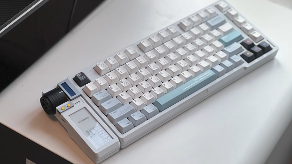
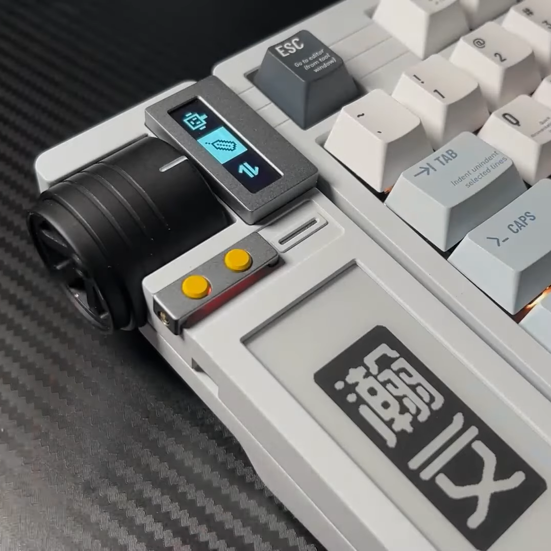
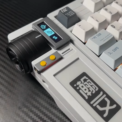 That is brilliant, but what makes this project really interesting is an extension module on the left side of the keyboard that turns it into what [Zhihui] calls a “smart keyboard”. The bottom part of this module has an E-ink display that can show a variety of useful information: current memory usage, email notifications or simply the weather forecast.
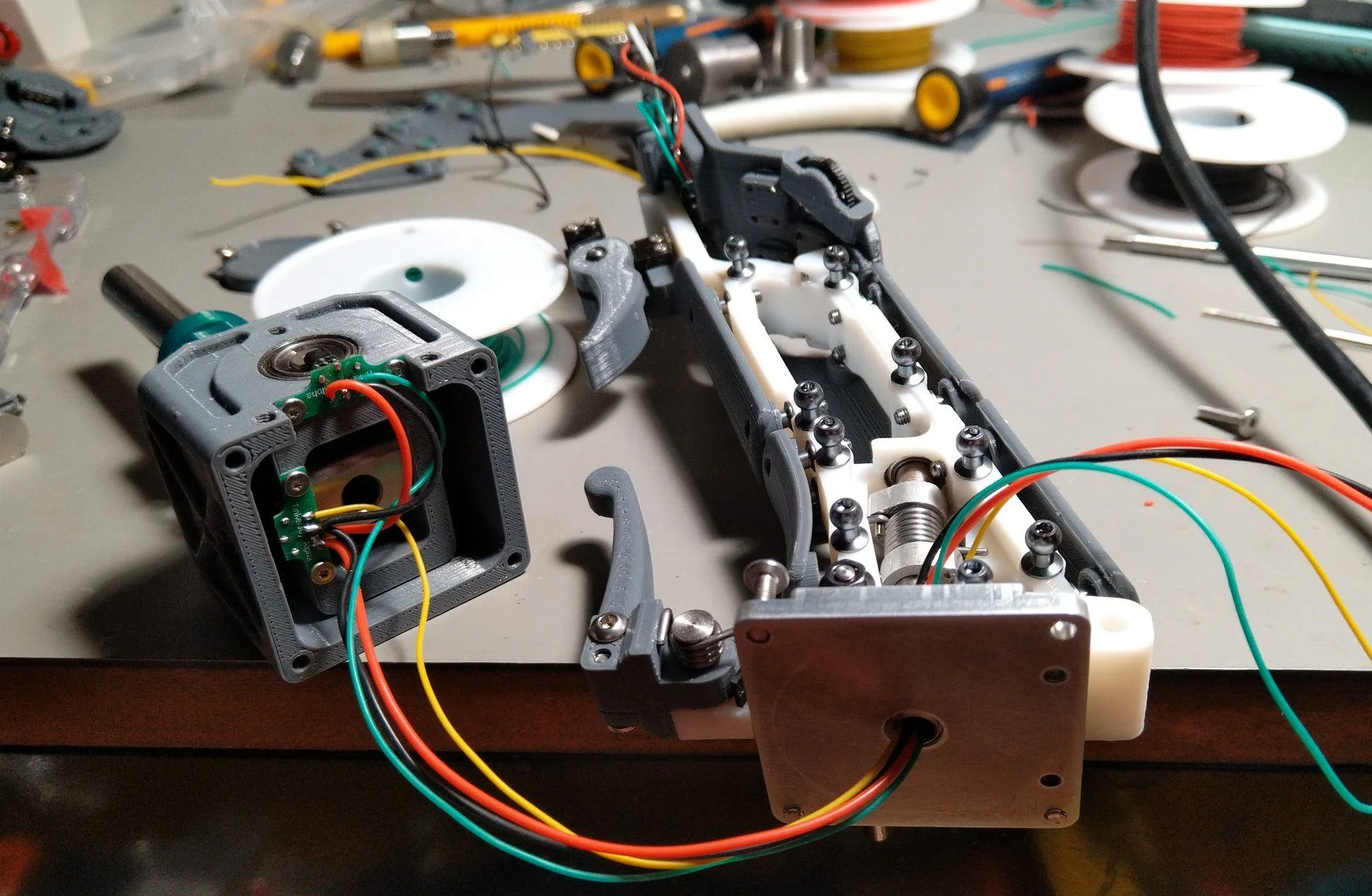
Next to the big E-ink screen is a tiny OLED display that works in tandem with a haptic feedback knob. Based on a brushless DC motor, this knob can be configured in various ways to perform several different tasks. It can be set to friction-less spinning mode, which is useful for quickly scrolling through long documents. It can become a multi-level switch to enable or disable features, or a volume knob with virtual end stops. There’s even an option to use it as a physical indicator for things like the current CPU usage.
The keyboard also houses a USB hub to attach other gadgets, as well as a lithium battery to power the haptic knob, since it uses more power than a standard USB 2.0 port can deliver. There’s even a little capacitive touch strip below the space bar, which allows you to use one of your thumbs to switch between different tabs or to use quick copy/paste functions.
If all of this sounds like your idea of a perfect keyboard, then you’ll be pleased to hear that [Zhihui] plans to open-source all hardware and software designs once he’s cleaned up his code. Until that time, you may want to read up on the working principle of a haptic smart knob, or find out what’s the most efficient way to read out a certain number of buttons with a microcontroller.
Continue reading “Smart Modular Keyboard Sports An E-ink Display And A Haptic Feedback Knob” →

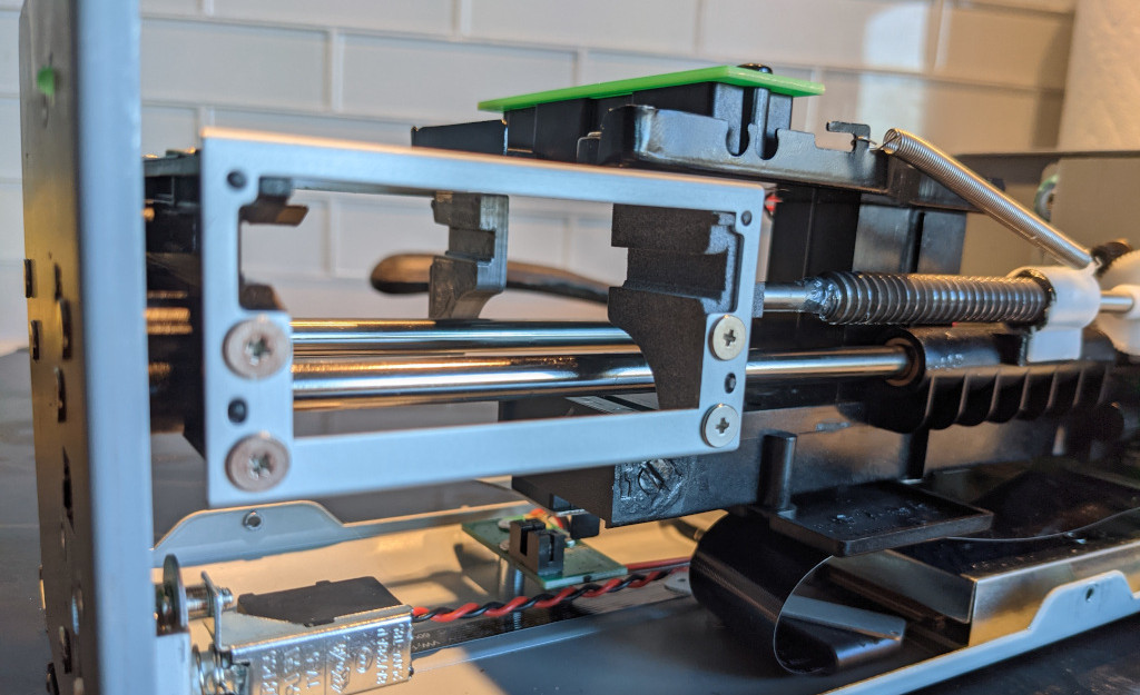 On the software side, [Christian] modified a driver for the Plustek 8100 so that it sweeps the scan head further than usual. At the application level, to scan medium format frames, it does a total of four scans: one for each quadrant. The results get stitched together in software with a thoughtfully-designed shell script that provides previews and handles failures and restarts gracefully.