Old radios often had selenium rectifiers to convert AC to DC. The problem is that the old units, dating back to 1933, are prone to failure and to release dangerous chemicals like hydrogen selenide. [M Caldeira] has a new board made to fit a particular rectifier and also allows a varying voltage drop. The circuit consists of a few diodes, a MOSFET, and a pot for adjusting the voltage drop. An IRF840 MOSFET provides the adjustment.
Did it work? It did. The good news is that if it fails — which shouldn’t happen very often — it won’t release stinky and noxious fumes
We wondered if he should 3D print a fake case to make it look more the part. If you haven’t seen a real selenium rectifier, they were made of stacks of metal plates coated with bismuth or nickel. Then, a film of doped selenium was annealed to the surface to form cadmium selenide. Each plate could handle about 20 V and the more plates you used, the more reverse voltage the device could withstand.
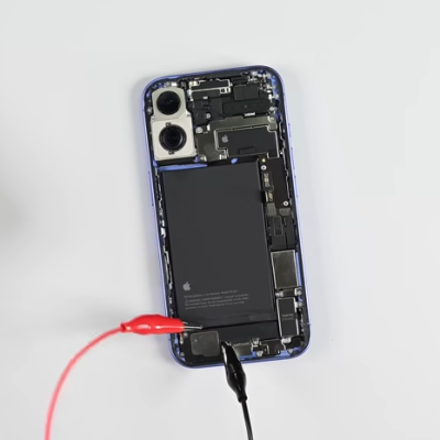
There’s a wild new feature making repair jobs easier (not to mention less messy) and iFixit covers it in their roundup of the iPhone 16’s repairability: electrically-released adhesive.
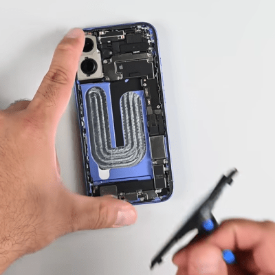
Here’s how it works. The adhesive looks like a curved strip with what appears to be a thin film of aluminum embedded into it. It’s applied much like any other adhesive strip: peel away the film, and press it between whatever two things it needs to stick. But to release it, that’s where the magic happens. One applies a voltage (a 9 V battery will do the job) between the aluminum frame of the phone and a special tab on the battery. In about a minute the battery will come away with no force, and residue-free.
9V does the job in about a minute, but up to 30 V can be used.
The battery comes away cleanly and without leaving residue.
There is one catch: make sure the polarity is correct! The adhesive releases because applying voltage oxidizes aluminum a small amount, causing Al3+ to migrate into the adhesive and debond it. One wants the adhesive debonded from the phone’s frame (negative) and left on the battery. Flipping the polarity will debond the adhesive the wrong way around, leaving the adhesive on the phone instead.
Some months ago we shared that Apple was likely going to go in this direction but it’s great to see some hands-on and see it in action. This adhesive does seem to match electrical debonding offered by a company called Tesa, and there’s a research paper describing it.
A video embedded below goes through the iPhone 16’s repairability innovations, but if you’d like to skip straight to the nifty new battery adhesive, that starts at the 2:36 mark.
Nothing can ruin a restoration project faster than broken knobs. Sure, that old “boat anchor” ham rig will work just fine with some modern knobs, but few and far between are the vintage electronics buffs that will settle for such aesthetic affrontery. But with new old stock knobs commanding dear prices, what’s the budget-conscious restorationist to do? Why, fix the cracked knobs yourself, of course.
At least that’s what [Level UP EE Lab] tried with his vintage Heahkit DX60 ham transmitter, with pretty impressive results. The knobs on this early-60s radio had all cracked thanks to years of over-tightening the set screws. To strengthen the knobs, he found some shaft collars with a 1/4″ inside diameter and an appropriate set screw. The backside of the knob was milled out to make room for the insert, which was then glued firmly in place with everyone’s go-to adhesive, JB Weld. [Level UP] chose the “Plastibonder” product, which turns out not to be an epoxy but rather a two-part urethane resin, which despite some initial difficulties flowed nicely around the shaft collar and filled the milled-out space inside the knob. The resin also flowed into the channels milled into the outside diameter of the shaft collars, which are intended to grip the hardened resin better and prevent future knob spinning.
It’s a pretty straightforward repair if a bit fussy, but the result is knobs that perfectly match the radio and still have the patina of 60-plus years of use. We’ll keep this technique in mind for our next restoration, or even just an everyday repair. Of course, for less demanding applications, there are always 3D printed knobs.
There’s a special kind of satisfaction found in the act of repairing a previously broken device, which is why YouTube is full of repair channels and guides on how to do it yourself. Inspired by this, [Doug Brown] decided to give it a shot himself, with an Elgato HD60 S HDMI capture device as the patient. As per the eBay listing, the device did not show up as a USB device when connected to a computer — a quick probing of the innards revealed that not only were the board voltages being dragged down, but some of the components on the PCB were getting suspiciously hot.
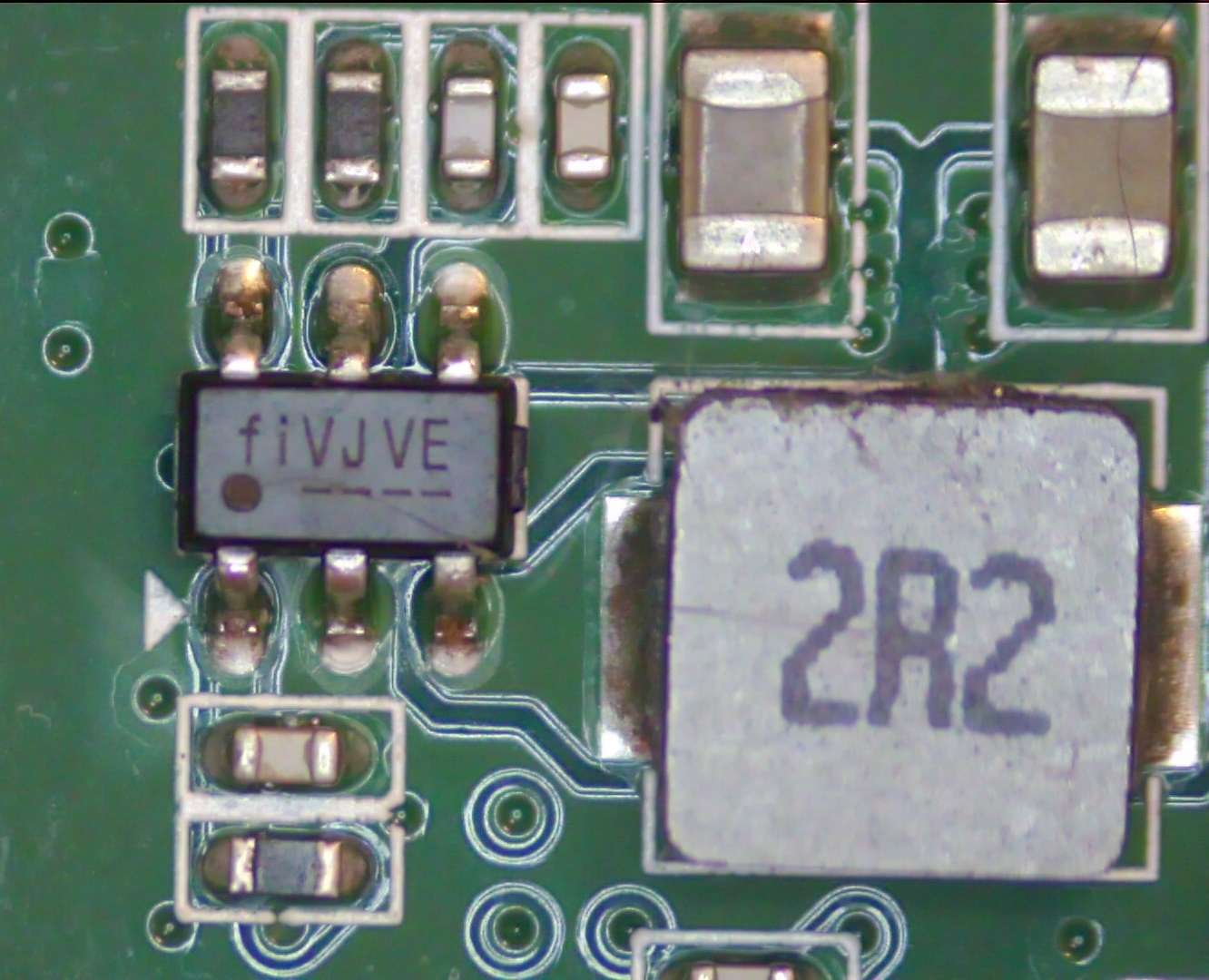
One of the broken switching regulators on the Elgato HD60 S capture device PCB. (Credit: Doug Brown)
On a thermal camera the hot components in question turned out to part of the voltage regulator circuits, one a switching regulator (marked fiVJVE, for Fitipower FP6373A) and another a voltage inverter marked PFNI (Ti TPS60403DBV).
Since both took 5 V, the suspicion was an over-voltage event on the USB side. After replacing the FP6373A and TPS60403 with newly purchased ones, the voltage rails were indeed healthy, and the Elgato sprung to life and could be used for HDMI capture and pass-through. However, the device’s onboard LEDs stubbornly refused to follow the boot-up pattern or show any other color patterns. Was this just a busted Innotech IT1504 LED driver IC?
Swapping it with a pin-compatible Macroblock MB15040 didn’t improve the situation, and the LEDs worked fine when externally controlling the MB15040 on its SPI bus, as well as with the original IT1504. Asking Elgato whether there was a known issue with these status LEDs didn’t lead to anything, so [Doug] decided to tackle the presumed source of the problem: the Nuvoton M031LD2AE MCU that’s supposed to drive the LED driver IC. The PCB helpfully provides a 4-pin JST connector on the board for the MCU’s SWD interface, but Elgato did protect the flash contents, so a straight dump wasn’t going to work.
The binary firmware is however helpfully available from Elgato, with the MCU already running the latest version. This is the point where [Doug] loaded the firmware into Ghidra to begin to understand what exactly this firmware was supposed to be doing. Putting on a fresh MCU with the correct firmware definitely worked, but debugging was hard as the new MCU also enabled protections, so in Ghidra the offending code for this was identified and neutralized, finally allowing for on-chip debugging and leading down another rabbit hole only to find an SPI flash chip at the end.
Ultimately it turned out that all the hardware was working fine. The problem ended up being that the LED patterns stored on the SPI EEPROM had become corrupted, which caused the Nuvoton MCU to skip over them. The same issue was confirmed on a second HD60 S, which makes it seem that this is a common issue with these Elgato capture devices. As a next step [Doug] hopes to figure out a way to more easily fix this issue, as even the streamlined process is still quite convoluted. Whether it is an issue with Elgato’s software or firmware (updater) is unknown at this point, but at least there seems to be a fix for now, even if Elgato support seems to just tell owners to ‘ignore it if capturing works’.
For vintage calculator fans, nothing strikes more fear than knowing that someday their precious and irreplaceable daily driver will become a museum piece to be looked at and admired — but never touched again. More often than not, the failure mode will be the keypad.
In an effort to recover from the inevitable, at least for 70s vintage TI calculators, [George] has come up with these nice replacement keypad PCBs. The original membrane switches on these calculators have a limited life, but luckily there are ultra-slim SMD tactile switches these days make a dandy substitute. [George] specifies a 0.8 mm thick switch that when mounted on a 1.6 mm thick PCB comes in just a hair over the original keypad’s 2.2 mm thickness. He has layouts for a TI-45, which should also fit a TI-30, and one for the larger keypads on TI-58s and TI-59s.
While these particular calculators might not in your collection, [George]’s goal is to create an open source collection of replacement keypads for all the vintage calculators sitting in desk drawers out there. And not just keypads, but battery packs, too.
[MIKROWAVE1] claims he’s not a radio repair guy, but he agreed to look at a malfunctioning Hallicrafters S-120 shortwave receiver. He lets us watch as he tries to get it in shape in the video below. You’ll see that one of his subscribers had done a great job restoring the radio, but it just didn’t work well.
Everything looked great including the restored parts, so it was a mystery why things wouldn’t work. However, every voltage measured was about 20V too low. Turns out that the series fuse resistor had changed value and was dropping too much voltage.
It is common these days to have a soldering iron where you can set the temperature using some sort of digital control. But how accurate is it? Probably pretty accurate, but [TheHWCave] picked up a vintage instrument on eBay that was made to read soldering iron temperature. You can see the video below, which includes an underwhelming teardown.
The device is a J thermocouple and a decidedly vintage analog meter. What’s inside? Nearly nothing. So why did the meter not read correctly? And where is the cold junction compensation?