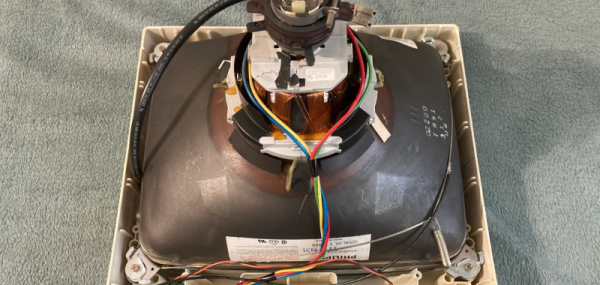
Nothing quite says vintage computer like a dedicated glass terminal. We enjoyed [Adam]’s restoration of an Acorn CRT monitor. The 14 inch display had a common problem: a defective power switch. Replacing a switch shouldn’t be a big deal, of course, but these old CRT monitors have exciting voltages inside and require special care.
One common issue, for example, is the fact that the old CRTs are really large capacitors and can hold a dangerous charge for some time. The easiest way to handle the potential problem is to make sure the device is unplugged, ground a screwdriver blade, and push the blade under the second anode cap. Most of the time, nothing happens. Once in a while, though, you’ll hear a loud pop and you just saved yourself a nasty shock.
Even though the actual repair was pretty mundane, the teardown was a great nostalgia trip and while we don’t want to give up our LCD, we do like the old glass. CRTs have a long history and came a long way before their last gasps. They even took a turn as mass storage devices.
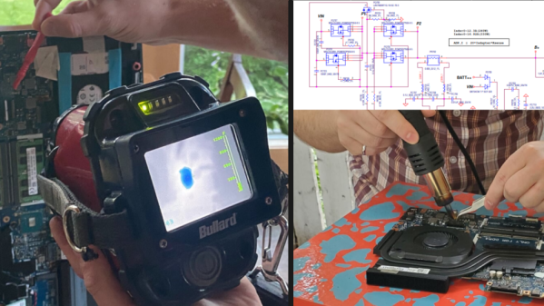
It started with a friend’s Alienware laptop that would only boot to a black screen and get very hot in the process. With the help of a thermal imaging camera and some schematics, [Troy] was able to see that one of the closely-spaced MOSFETs in the power supply appeared to be the culprit. Swapping the power MOSFETs out with replacements seemed a reasonable approach, so armed with a hot air rework station he got to work. But that’s where problems began.
The desoldering process was far from clean, in part because the laptop’s multi-layer PCB had excellent thermal management, sucking away heat nearly as fast as [Troy]’s hot air gun could lay it down. It ended up being a messy slog of a job that damaged some of the pads. As a result, the prospects of soldering on a replacement was not looking good. But reviewing the schematic and pondering the situation gave [Troy] an idea.
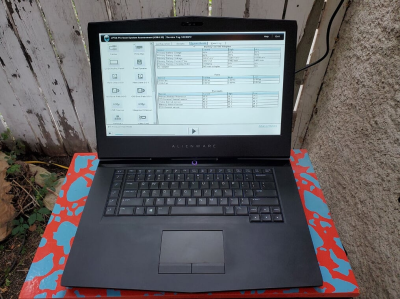
One expensive laptop, brought back to service.
According to the schematic, the two MOSFETs (at least one of which was faulty) had parallel counterparts on the other side of the board. This is typically done to increase capacity and spread the thermal load somewhat. However, according to the current calculations on the schematic, these parts are expected to handle about 20 A in total, but the datasheets show that each of the MOSFETs could handle that kind of current easily (as long as heat sinking could keep up.) In theory, the laptop didn’t need the extra capacity.
Could the laptop “just work” now that the faulty part had simply been removed? [Troy] and his friend [Mike] were willing to give it a shot, so after cleaning up the mess as best they could, they powered the laptop on, and to their mild surprise, everything worked! Some stress testing with intensive gaming showed that the thermal problems were a thing of the past.
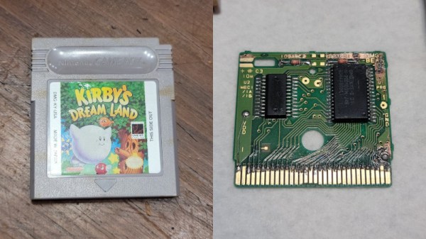
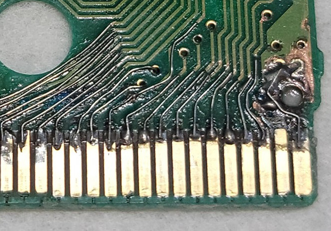
Retro consoles and handhelds are full of nostalgia and happy memories for many. However, keeping these machines and their media going can be a difficult job at times. [Taylor] was challenged to rescue a copy of Kirby’s Dream Land for the original Game Boy, and set about the task.
The cartridge was badly corroded, with many of the traces eaten through, rendering the game inoperable. First, all the components were removed, and the board was cleaned. This allowed easy access to the traces across the whole board. Then, the job was to delicately remove some solder mask from the parts of the traces still remaining, and bridge the gaps with fine copper wire. Even worse, several vias were damaged, which [Taylor] tackled by feeding jumper wires through the board and executing a repair on each side.
It’s a simple enough repair for the experienced hand, but virtually magic to a retro gaming fan that doesn’t know how to solder. [Taylor] has given us a great example of how to deal with corroded carts properly, with enough detail to be quite educational to the beginner.
It would be fair to say that the Internet as we know it runs on Cisco hardware. While you might never see the devices first-hand, there’s an excellent chance that every web-bound packet leaving your computer or smartphone will spend at least a few milliseconds of its life traveling through hardware built by the San Jose, California based company. But of course, even a telecommunications giant like Cisco had to start somewhere.
Cisco’s first commercial router, the Advanced Gateway Server (AGS), was released in 1986 and helped put the company (and the Internet) on the path towards unfathomable success. [Andreas Semmelmann] had wanted to add one of these microwave-sized machines to his collection for some time, so when an AGS+ popped up in the local classifieds he didn’t hesitate to make the hour drive to go pick it up. But like many pieces of vintage computing equipment, it needed a little help getting back on its feet.
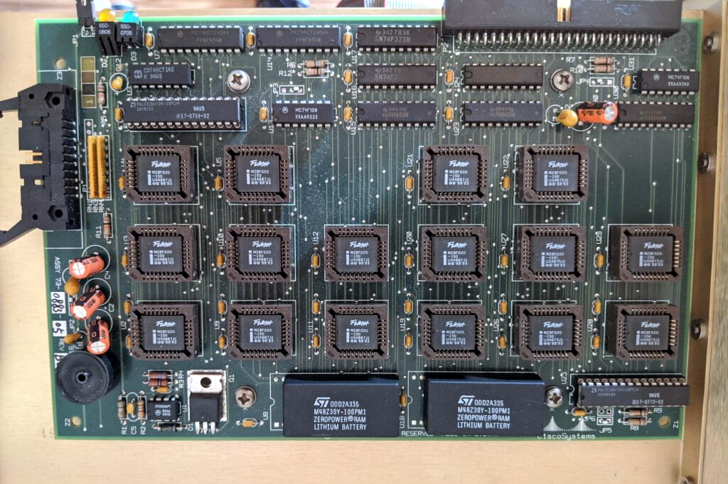
What 4 MB of flash looked like in the late 1980s.
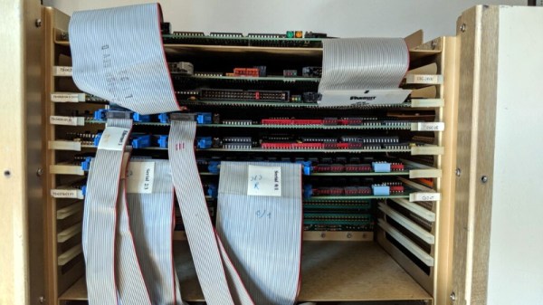
Since he had to take the router apart anyway to diagnose what ailed it, [Andreas] decided to take photographs along the way and document this piece of Internet history. He walks the reader through the massive processor, Ethernet, and serial cards that are housed in the unit’s rack-like enclosure. We appreciate him taking the scenic route, as it gives us a great look inside what would have been state-of-the-art telecommunications gear when this version of the AGS hit the market in 1989.
The walk-through is full of interesting details that make us appreciate just how far things have come in the last 32 years. Imagine yanking the EPROMs out of the board and firing up the UV eraser each time you needed to update your router’s firmware. Or needing a special adapter to convert the AUI-15 connectors on the back panel to the now ubiquitous RJ45 jack.
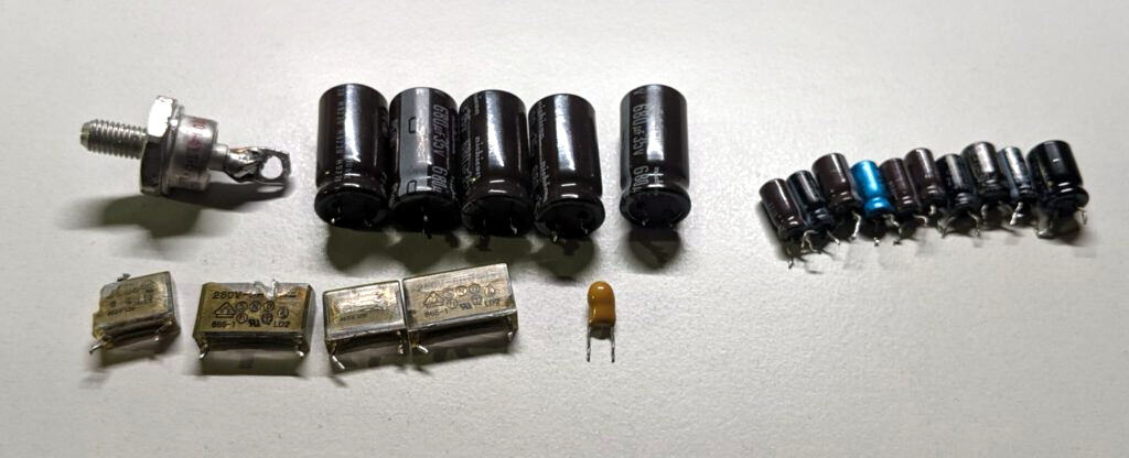
After this stroll down memory lane, [Andreas] gets to the actual repair work. It likely won’t surprise the regular Hackaday reader to find that the power supply wasn’t operating to spec, and that some aged capacitors and a shorted rectifier diode needed to be replaced to put it back on an even keel. But even with the PSU repaired, the router failed to start. The console output indicated the software was crashing, but hardware diagnostics showed no obvious faults.
Replacing these failed PSU components was just the beginning.
With some part swapping, firmware flashing, and even a bit of assistance from Cisco luminary [Phillip Remaker], the issue was eventually identified as a faulty environmental monitoring (ENVM) card installed in the AGS+. As luck would have it the ENVM capability isn’t required to boot the router, so [Andreas] was able to just disconnect the card and continue on with his exploration of the hardware that helped build the Internet as we know it.
Anyone who’s ever had to deal with the aftermath of a leaking battery knows how much damage such a failure can cause. Degrading batteries leak corrosive chemicals that eat away PCB traces, clog up connectors and generally leave everything looking nasty. Getting your gadget working again usually calls for lots of scrubbing, followed by patiently tracing suspect connections and restoring any broken ones.
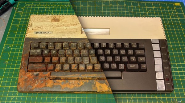
We doubt, however, that anyone has ever gone through as much effort as [Lee Smith] has on his Atari 800 XL. This example was listed on eBay in a severely damaged state, having been stored under an entire box of leaking batteries. [Lee] put in a bid and, to his own bemusement, won the auction. He was now the proud owner of a classic gaming machine which was covered in a thick brown crust of battery residue.
A first inspection showed that the damage was more than skin-deep: even inside the computer’s case it was one big mess of crusty brown junk. [Lee] first spent several hours on the plastic case, using different cleaning agents and an ultrasonic bath, and managed to get the case almost spotless again. The keyboard presented a larger challenge however: not only did it require thorough cleaning of every single switch and keycap, the keyboard’s matrix on the PCB had several connections missing, which had to be restored using bodge wires.
With the keyboard working again, [Lee] turned to the mainboard. This turned out to be an even greater challenge, with several components (including a few custom chips) damaged beyond repair. With the help of a few eBay replacements parts and (again) countless hours of scrubbing, the mainboard started to look healthy again. After a few tests, [Lee] felt confident enough to hook up the entire system and turn it on. And his efforts had paid off: the battered Atari dutifully displayed its BASIC prompt, ready for its second lease of life.
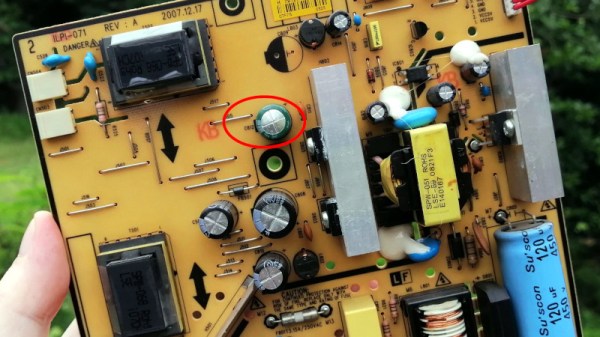
It’s quite a while since any of us unpacked a brand new VGA monitor, but since so many machines still have the ability to drive them even through an inexpensive adaptor they’re still something that finds a use. With so many old VGA flat panel monitors being tossed away they even come at the low low price of free, which can’t be argued with. CNXSoft’s [Jean-Luc Aufranc] was tasked with fixing a dead one, and wrote an account of his progress.
Seasoned readers will no doubt be guessing where this story will lead, as when he cracked it open and exposed the PSU board there was the tell-tale puffiness of a failed electrolytic capacitor. For relative pennies a replacement was secured, and the monitor was fixed. As repair hacks go it’s a straightforward one, but still worth remarking because a free monitor is a free monitor.
We called the demise of VGA back in 2016, and have seen no reason to go back on that. But for those of us left with a few legacy monitors it’s worth remembering that DVI and thus the DVI compatibility mode of HDMI is little more than a digitised version of the R, G, and B channels you’d find on that trusty blue connector. Maybe that little dongle doesn’t make such a bad purchase, and of course you can also use it as an SDR if you want.
Whether you’re making, repairing, or hacking something together, we all need fastners. Screws, nuts and bolts, and pop rivets are handy sometimes. Various resins and even hot glue are equally useful. In some cases however the right fastener for the job eludes us, and we need another trick up our sleeve.
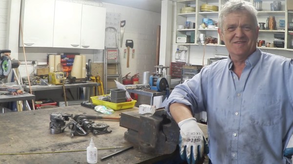
[Robert Murray-Smith] found himself in such a position. His goal was to join two pieces of aluminum that need a nice finish on both sides. Neither glue, pop rivets, screws, nuts or bolts would have been appropriate. [Robert] is always flush with ideas both new and old, and he resorted to using an old school fastener as explained as explained in his video “How To Make And Use Rivets“.
In the video below the break, [Robert] goes into great detail about making a simple rivet die from a 5 mm (3/16”) piece of flat steel, creating the rivet from a brass rod, and then using the flush rivet to join two pieces of aluminum. The simple tooling he uses makes the technique available to anybody with a propane torch, a vise, some basic tools, and a simple claw hammer. We also appreciate [Robert]’s discussion of cold riveting, hot riveting, and annealing the rivets as needed.
Not only is riveting a technique thousands of years old, its advancement and application during the Industrial Revolution enabled technologies that couldn’t have existed otherwise. Hackaday’s own [Jenny List] did a wonderful write-up about rivets in 2018 that you won’t want to miss!