The Clock, Another Way To Modify The Sound Of A Synth Chip

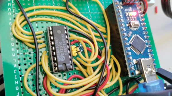
The Philips SAA1099 is perhaps one of the lesser-known among the crop of 1980s-era 8-bit sound generator chips, but with three stereo voices onboard it makes a capable instrument for chiptune experimentation. It’s attracted the attention of [Folkert van Heusden], who’s tried the novel experiment of seeing what happens when a sound chip’s clock is varied.

A quick search of the internet reveals that the chip, which appeared in early Sound Blaster cards, is intended to have an 8 MHz clock. He’s hooked it up to an Arduino as a variable clock source, which surprised us but it seems an ATmega328’s timer is faster than we expected.

There are a couple of WAV files, and as expected the clock frequency has a significant effect on the pitch. The samples just sweep up and down without much attempt at making a sound you’d want to hear, but it does raise an interesting possibility of adding a further pitch bending ability to the capabilities already in the chip. When these circuits were new we couldn’t control a clock on a whim with the 8-bit processors of the day, so of course none of us thought to try this at the time. He’s tried it, so you don’t have to.

The SAA1099 has been mentioned in these pages only once, as a chip used in peripherals for 1980s Czech computers.

Vintage Computer Festival Southern California

The Vintage Computer Festival is coming to sunny Southern California in February 2024. That’s right, bring your Commodores, your Tandys,  your PDP-11s, and Altairs. The world of retrocomputing will be open to vendors, visitors, and exhibitors at The Hotel Fera Events Center in Orange, California on February 17th and 18th, 2024.

If you’re thinking there already is a VCF out west, you’d be right. VCF West was held in August at the Computer History Museum. The CHM is in Mountain View, California. That puts it nearly at the epicenter of the microcomputer revolution of the ’70s and ’80s.

Southern California still had plenty of computer enthusiasts though. For the non-geographically inclined amongst us, SoCal is nearly 6 hours from Mountain View by car.  We’re sure we’ll see many familiar faces at SoCal, along with plenty of new ones.

The Vintage Computer Federation holds several events across the country each year. You might have heard some music from VCF Midwest 2023 back in September. Hackaday was also out in force at VCF East this year, where our own [Bil Herd] moderated a panel of vintage computer YouTubers including [Usagi Electric], [Adrian’s Digital Basement], and [FranLab].

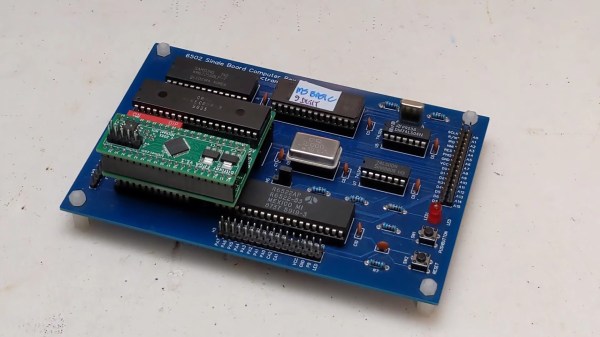
A 6502-based single-board computer with a ROMulator attached

Debug Your Senile Computers With The ROMulator

Some of you may have heard of the ROMulator, a device that can emulate RAM and ROM on 6502-based computers. But how does it work? How do you use it? What computers is it compatible with? [Jeff Tranter] covers that and more in his review of the ROMulator 6502.

The ROMulator is an FPGA-based board that slots between the 6502 and its socket on whatever computer it came from. It can emulate, but not intercept, accesses to RAM and ROM, which can be used to e.g. replace a ROM that you’re swapping very often or expand the RAM available to the CPU.

In his review, [Jeff] shows the ROMulator in action many computers, notably his custom 6502-based computer, a replica of an Apple 1 and two different replicas of the SUPERBOARD 2. He shows how the ROMulator can be configured, tested, used to debug the computers and even expand their RAM. Overall, [Jeff] thinks it’s a useful 6502 debugger that would have saved him lots of time in the past and we definitely agree.

Continue reading “Debug Your Senile Computers With The ROMulator” →

[Ken] Looks At The 386

The 80386 was — arguably — Intel’s first modern CPU. The 8086 was commercially successful, but the paged memory model was stifling. The 80286 also had a protected mode, which differed from the 386’s. [Ken Shirriff] takes the 386 apart for us in a recent blog post.

The 286’s protected mode was less successful than the 386 because of several key limitations as it was a 16-bit processor with a 24-bit address bus. It still required segment changes to access larger amounts of memory, and it had no good way to call back into real mode for compatibility reasons. The 386 fixed all that. You could adopt a segment strategy if you wanted to. But you could also load the segment registers once to point to a 4 GB linear address space and then essentially forget them. You also had a virtual 86 mode that could simulate real mode with some work.

The CPU used a 1-micron process, compared to the 1.5-micron process used earlier. The chip had 285,000 transistors (although the 80386SL had many more). That was ten times the number of devices on the 8086. The cheaper 386SX did use the 1.5 micron process for a while, but with a 16-bit external bus, this was feasible. While 285,000 sounds like a lot, a Core i9 has around 4.2 billion transistors. Times have changed.

A smaller design also allowed chips like the 386SL for laptops. The CPU took up only about a fourth of the die. The rest held bus controllers and cache interfaces to cut costs on laptops. That’s why it had so many more transistors.

[Ken] does his usual in-depth analysis of both the die and the history behind this historic device. We spent a lot of time writing protected mode 386 code, and it was nice to see the details of a very old friend. These days, you can get a pretty capable CPU system on a solderless breadboard, but designing a working 386 system took a few extra parts. The 80286 was a stepping stone between the 8086 and 80386, but even it had some secrets to give up.

Restoration Of A Thinkpad 701C

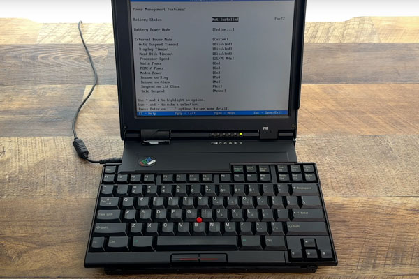
This is like ASMR for Hackers: restoration specialist [Polymatt] has put together a video of his work restoring a 1995 IBM Thinkpad 701c, the famous butterfly keyboard laptop. It’s an incredible bit of restoration, with a complete teardown and rebuild, even including remaking the decals and rubber feet.

[Polymatt] runs Project Butterfly, an excellent site for those who love these iconic laptops, offering advice and spare parts for restoring them. In this video, he does a complete teardown, taking the restored laptop completely apart, cleaning it out, and replacing parts that are beyond salvaging, like the battery, and replacing them. Finally, he puts the whole thing back together again and watches it boot up. It’s a great video that we’ve put below the break and is well worth watching if you wonder about how much work this sort of thing involves: the entire process took him over two years.

We’ve covered some of his work in the past, including the surprisingly complicated business of analyzing and replacing the Ni-Cad battery that the original laptop used. Continue reading “Restoration Of A Thinkpad 701C” →

Designing A Macintosh-to-VGA Adapter With An LM1881

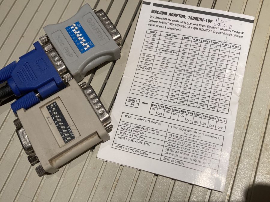
Old-school Macintosh-to-VGA adapter. Just solve for X, set the right DIP switches and you’re golden.

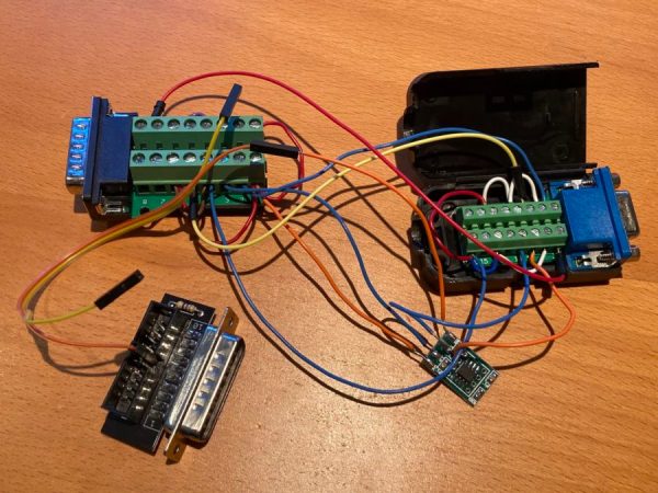
If you’re the happy owner of a vintage Apple system like a 1989 Macintosh IIci you may know the pain of keeping working monitors around. Unless it’s a genuine Apple-approved CRT with the proprietary DA-15-based video connector, you are going to need at least an adapter studded with DIP switches to connect it to other monitors. Yet as [Steve] recently found out, the Macintosh’s rather selective use of video synchronization signals causes quite a headache when you try to hook up a range of VGA-equipped LCD monitors. A possible solution? Extracting the sync signal using a Texas Instruments LM1881 video sync separator chip.

Much of this trouble comes from the way that these old Apple systems output the analog video signal, which goes far beyond the physical differences of the DA-15 versus the standard DE-15 D-subminiature connectors. Whereas the VGA standard defines the RGB signals along with a VSYNC and HSYNC signal, the Apple version can generate HSYNC, VSYC, but also CSYNC (composite sync). Which sync signal is generated depends on what value the system reads on the three sense pins on the DA-15 connector, as a kind of crude monitor ID.

Theoretically this should be easy to adapt to, you might think, but the curveball Apple throws here is that for the monitor ID that outputs both VSYNC and HSYNC you are limited to a fixed resolution of 640 x 870, which is not the desired 640 x 480. The obvious solution is then to target the one monitor configuration with this output resolution, and extract the CSYNC (and sync-on-green) signal which it outputs, so that it can be fudged into a more VGA-like sync signal. Incidentally, it seems that [Steve]’s older Dell 2001FP LCD monitor does support sync-on-green and CSYNC, whereas newer LCD monitors no longer list this as a feature, which is why now more than a passive adapter is needed.

Although still a work-in-progress, so far [Steve] has managed to get an image on a number of these newer LCDs by using the LM1881 to extract CSYNC and obtain a VSYNC signal this way, while using the CSYNC as a sloppy HSYNC alternative. Other ICs also can generate an HSYNC signal from CSYNC, but those cost a bit more than the ~USD$3 LM1881.

Implementing Commodore’s IEC Bus Protocol On A KIM-1 Single Board Computer

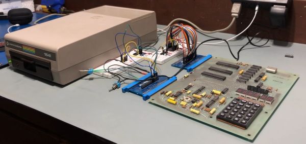
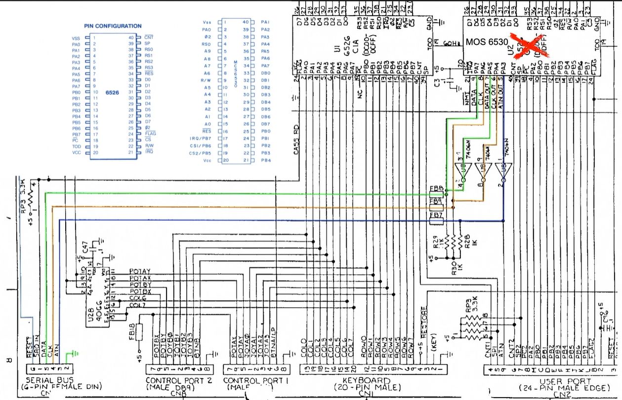
Although the PET is most likely the more well-known of Commodore’s early computer systems, the KIM-1 (Keyboard Input Monitor) single board computer was launched a year prior, in 1976. It featured not only the same MOS 6502 MPU as later Commodore systems, but also an MCS6530 PIO IC that contained the ROM, RAM and programmable I/O, reminiscent of later I/O chips on Commodore systems. As the KIM-1 was only designed to be used with an external tape drive (and a terminal for fancy users), adding a floppy drive like the ubiquitous 1541 with its IEC bus interface was not a first-party accessory. How the IEC bus can be retrofitted to a KIM-1 system is demonstrated in this video by the Commodore History channel.

The Commodore KIM-1 hardware is almost directly compatible with the C64 hardware. (Credit: Commodore History on YouTube)

What is most notable is just how similar the KIM-1 hardware is to later PET and VIC hardware, with the CIA and PIO ICs featuring the same requisite pins for this purpose, and requiring only the addition of an inverting (SN7406) IC and an EPROM featuring the new code to support the proprietary Commodore IEC bus protocol, which was mostly pilfered byte-for-byte from a C64 kernal ROM.

With some creative breadboarding in place and using nothing more than the on-board LED display and keyboard matrix, it was then possible to write to the inserted floppy disk, and also to read back from it. What’s interesting here is that this essentially replaces the tape drive as target for the KIM-1, which thus retains a lot of the original functionality, but with a big performance boost. While perhaps only interesting as an academic exercise, it’s definitely an interesting look at the early beginnings of what would blossom into the Commodore 64.

Continue reading “Implementing Commodore’s IEC Bus Protocol On A KIM-1 Single Board Computer” →