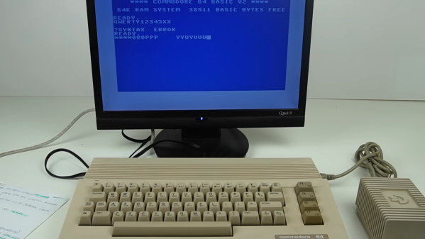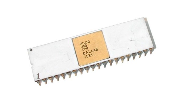
When it comes to famous operating systems for the Z80 and similar Zilog processors, the first and maybe only one to come to mind is CP/M, which was even made its presence known on the dual-CPU (8502 and Z80) Commodore 128. Yet Zilog also developed its own operating system, in the form of the comprehensively titled Z80 Operating System with Relocatable Modules and I/O Management (Z80-RIO for short). With limited documentation having survived, [Ralf-Peter Nerlich] has set out to retain and recover what information he can on RIO and the associated Programming Language Zilog (PLZ) after working with these systems himself when they were new.
Perhaps unsurprisingly, neither Z80-RIO nor PLZ were targeting the regular consumer market when they were brought to market in the late 1970s, but were part of Zilog’s focus on industrial markets, as well as laboratories and elsewhere that could benefit from a versatile, programmable computer system for control and automation.
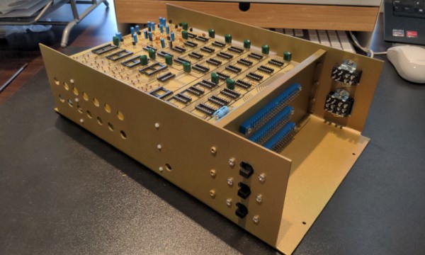
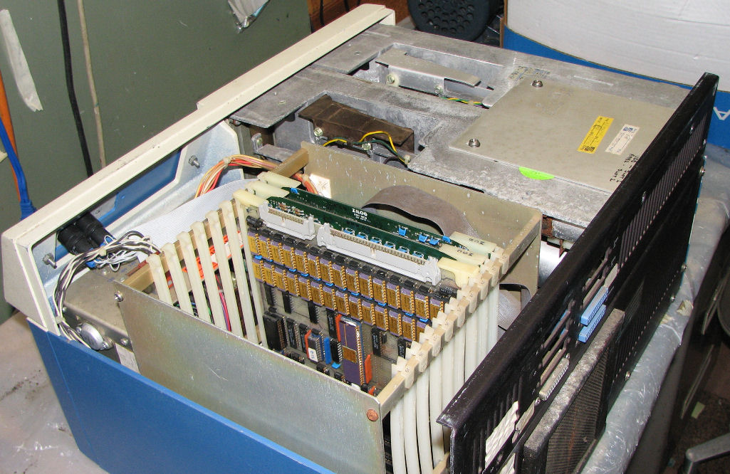
As part of an integrated hardware/software solution, Zilog released a series of computer systems, such as the MCZ 1/20 of which a number of examples survive today. Herb Johnson’s collection and restoration projects provide a good overview of not only the base systems, but also the expansion cards available for these systems. Right along with the Z80-RIO OS providing the ability to customize the system for the target usage, the underlying hardware could also be configured with just the expansion boards required, or conceivably even custom boards.
Of course, it doesn’t take many guesses to figure out what happened to Z80’s RIO OS and related, with the 1980s heralding massive shifts in the computer markets. Although now functionally obsolete for decades, it’s good to see such preservation efforts of 1970s computing systems and related software. These are after all the foundations on which modern day computing is built.
(Thanks to [Stephen Walters] for the tip)