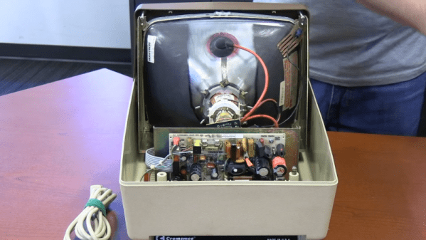
If you were around when the Altair 8800 was king, you might remember the name Cromemco. They were an early vendor of add-ons for the Altair, along with companies like Godbout and Morrow. The company was mostly famous for a very crude digital camera for the Altair and a similarly-crude graphics interface card. They graduated into building S-100 bus computers. Like many similar companies, they could taste the upcoming home PC market, and they wanted a piece of it. Their answer? The $1,800 C-10 Cromemco Personal Computer, and you can see [Vintage Geek’s] thoughts on the odd machine in the video below.
The system ran CP/M and, like many similar systems, got lost in the rush to get the IBM PC. Compared to other computers of the time, the C-10 was compact. The keyboard layout seems odd today, but there wasn’t really much standardization in those days.
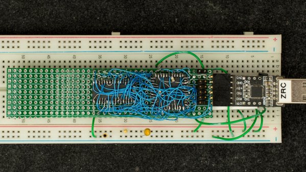
Retired hardware engineer [Plasmode] recently took on the challenge of building a debugger for the 6502 designed to sit atop the microprocessor while seated in a solder less breadboard. The result is the Diagnostic Overlay for W65C02 Breadboard, consisting of 128 kB SRAM and a 1250-gate CPLD. Except being 0.8 in wide, the overlay debugger is otherwise the same size as the 6502’s 40-pin DIP package, so it doesn’t overhang other portions of your circuit.
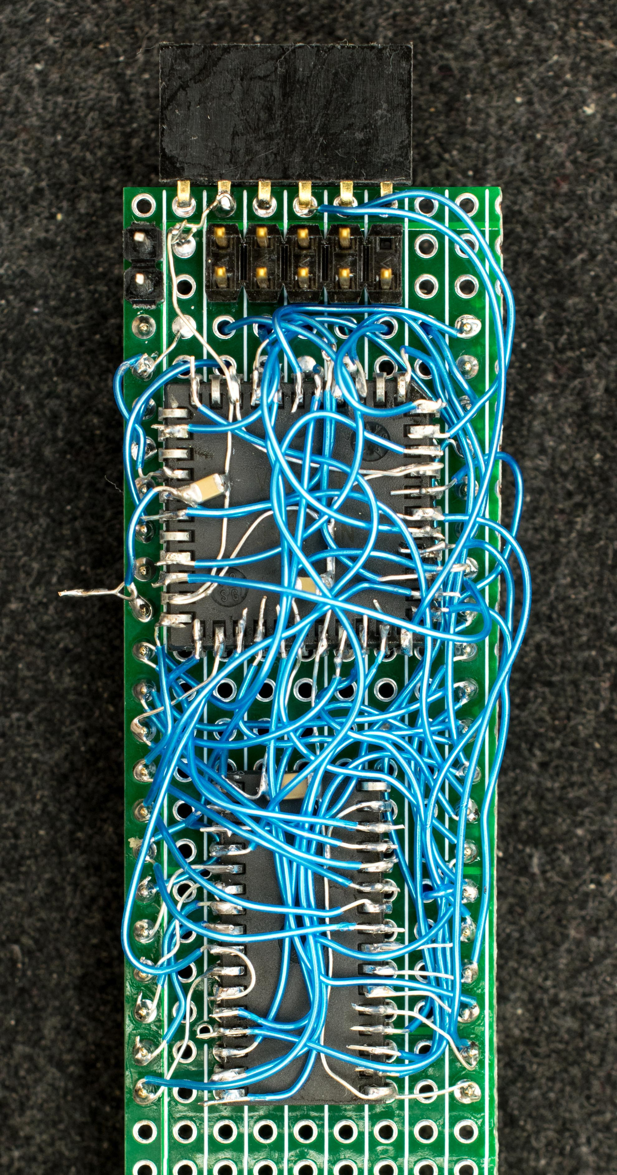
Being an initial concept prototype, [Plasmode] mounted the chips dead-bug style on perf board — a process he himself found tiring. If he builds additional debuggers, presumably he will consider making a PCB.
The prototype was constructed using point-to-point soldering with 30-ga wire wrap wire. It was all done under the inspection microscope. There are not many connections, but they are rather tedious so I can only do a dozen or so wires per session. It took me 2 days and several hours total to finish the prototype board.
This design is based on the CRC65 Frugal 6502 Single Board Computer, of course omitting the 6502 itself. Instead of a physical ROM memory chip, he implemented a 64-byte boot loader inside the CPLD and a serial port. This lets him to bootstrap the system over the serial port. He plans on expanding this to include other DIP-packaged retro microprocessors in the future. Check out his Hackaday.io project page ( above ). If you want to dig deeper, he posted the schematics here.
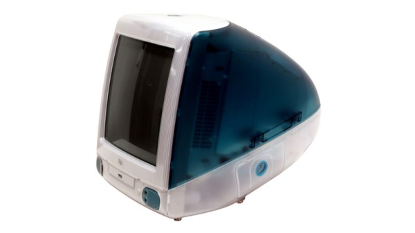
Growing older as an engineer turns out to be a succession of moments in which technologies and devices which you somehow still imagine to be cool or exciting, reveal themselves in fact to be obsolete, indeed, old. Such a moment comes today, with the25th anniversary of the most iconic of 1990s computers, Apple’s iMac. The translucent all-in-one machine was and remains more than simply yet another shiny Mac, it’s probably the single most influential home computer ever. A bold statement to be sure, but take a look at the computer you’re reading this on, indeed at all your electronic devices here in 2023, before you dismiss it.
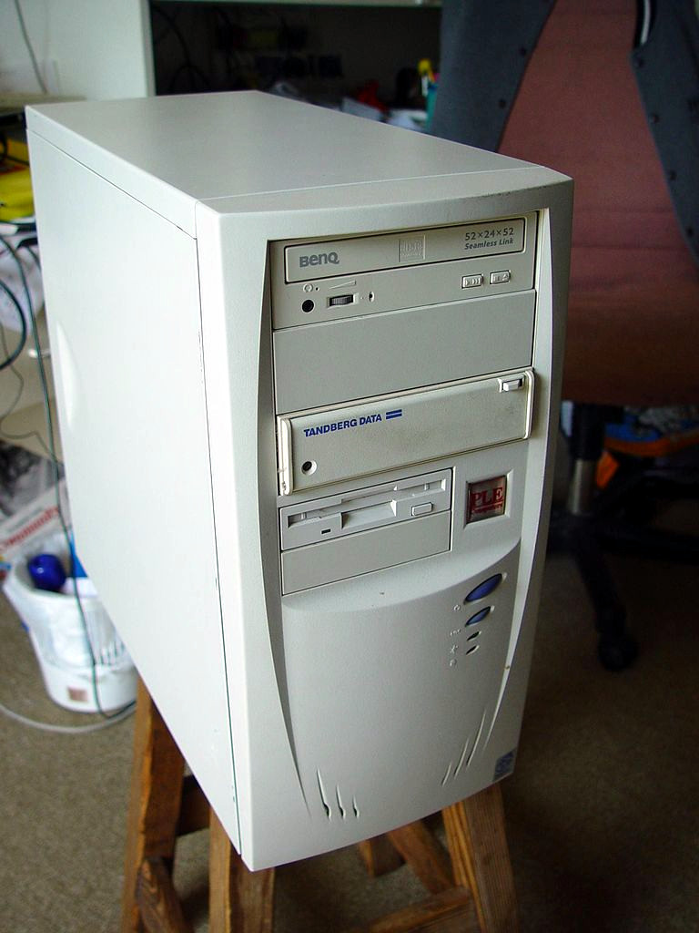
Any colour you want, as long as it’s beige. Leon Brooks, Public domain.
Computers in the 1990s were beige and boring. Breathtakingly so, a festival of the generic. If you had a PC it came in the same beige box as every single other PC, the only thing breaking the monotony being one of those LED 7-segment fake-MHz displays. Apple computers took the beige and ran with it, their PowerMac range being merely a smoother-fronted version of all those beige-box PCs. This was the period following the departure of Steve Jobs during which the company famously lost its way, and the Bondi blue Jonny Ive-designed iMac was the signature product of his triumphant return.
That’s enough pretending to have drunk the Apple Kool-Aid for one article, so why are we marking this anniversary? The answer lies not in the iMac’s hardware, though its 233MHz PowerPC G3 and ATI graphics driving a 15″ CRT were no slouch for the day, nor even in its forsaking of all their previous proprietary interfaces for USB. Instead it’s the design influence of this machine, as it ushered in a new era of technological devices whose ethos lay around how they might be used rather than in simply showering the interface with features. At the time the iMac spawned a brief fashion for translucent blue in everything from peripherals to steam irons, but in the quarter century since your devices have changed immeasurably in its wake. We still don’t like that weird round mouse though.
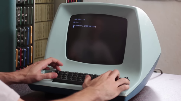
[David] at Usagi Electric ended up with an old Lear Siegler ADM-3A terminal in a trade a couple of years ago. But the CRT face was plagued with so-called cataracts, and the condition of the insides was unknown. The video ( below the break ) shows the restoration process, which went quite smoothly. [David] was relieved that the CRT repair in particular was easy, a fact he attributes to the Texas weather —
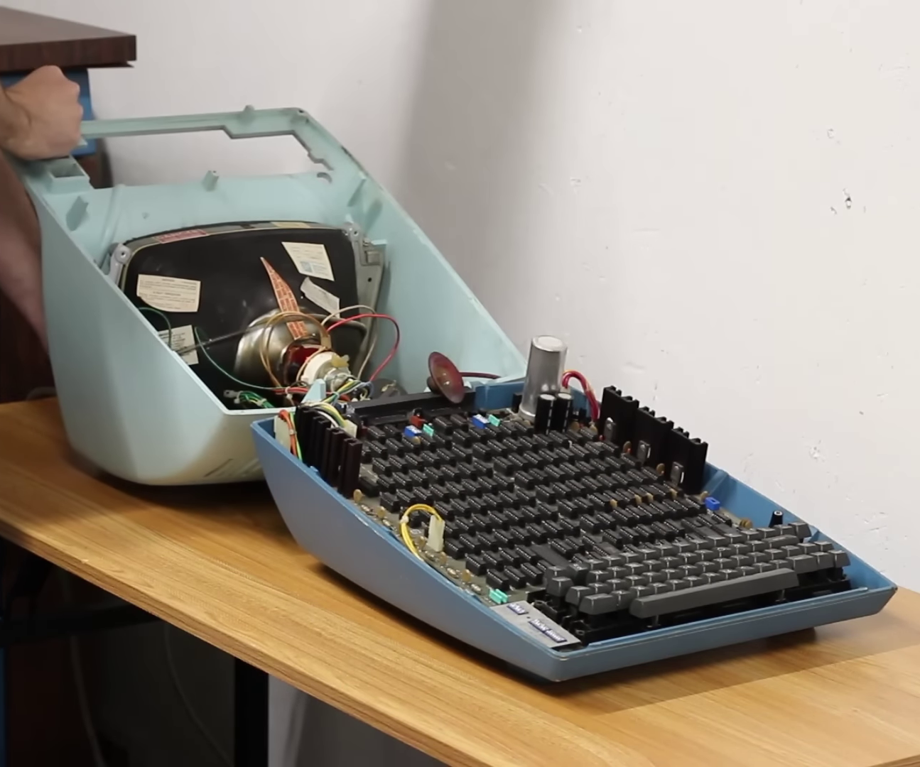
ADM-3A Under the Hood
The temperature was 110 F / 43 C when he set the CRT outside to bake in the sun for a few hours. Afterwards, removing the “integral implosion protection” plastic screen went better than expected. Everything cleaned up nicely and the screen reinstalled. Introduced in 1976, the main electronics board is chock full of TTL chips with nary a microprocessor in sight. Fortunately the board was substantially intact, and a single missing chip was found hidden underneath the board. [David] gets the terminal up and running in short order, and is confronted with an annoyance familiar to gray-haired programmers who grew up in this era. Most terminals had different sets of commands to control features such as cursor control and clearing parts or all of the screen. Programs often assumed a certain type of terminal. Some terminals could be configured to behave in different ways, and some programs offered the user a choice of terminals. Today your terminal emulator probably still has a few choices of which kind of terminal to emulate, VT-100 being the most common. And eventually some operating systems provided a terminal abstraction, like Unix’s termcap for example.
If you were around in the era where terminals like the ADM-3A were scattered everywhere, what was your favorite terminal and/or terminal feature? And today, do you have any favorite terminal emulator to recommend? Let us know in the comments below.
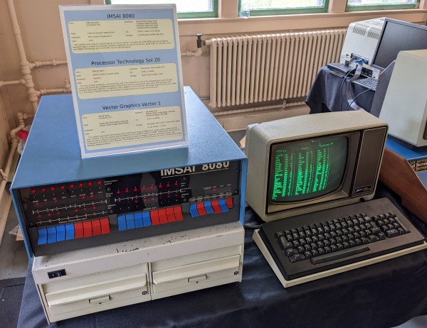
I recently dropped in on one of the Vintage Computer Festival events, and it made me think about why people — including myself — are fascinated with old computer technology. In my case, I lived through a lot of it, and many of the people milling around at VCF did too, so it could just be nostalgia. But there were also young people there.
Out of curiosity, I asked people about the appeal of the old computers on display there. Overwhelmingly, the answer was: you can understand the whole system readily. Imagine how long it would take you to learn all the hardware and software details of your current desktop computer CPU. Then add your GPU, the mass storage controllers, and your network interface. I don’t mean knowing the part numbers, specs, and other trivialities. I mean being able to program, repair, and even enhance it.
What’s the difference between a 64k ROM in a 28-pin DIP and a 128k ROM in a 32-pin DIP? Aside from the obvious answers of “64k” and “four pins,” it turns out that these two chips have a lot in common, enough so that it only takes a little bodging to make them interchangeable — more or less.
For a variety of reasons revealed in the video below, [Anders Nielsen] use the SST39SF010, a Flash ROM in a 32-pin DIP, in place of the old standby W27C512, an EEPROM in a 28-pin DIP. To deal with those pesky extra pins on the Flash ROM, [Anders] dug into the data sheets and found that thanks to JEDEC standards, almost everything about the pinouts of the two chips is identical. The only real difference is the location of Vcc, plus the presence of a 16th address bus line on the more capacious Flash ROM.
Willing to sacrifice the upper half of the Flash chip’s capacity, [Anders] set about bodging the 32-pin chip to work in a 28-pin socket. The mods include a jumper from pin 32 to pin 30 on the Flash chip, which puts Vcc in the right place, and adding a couple of pull-up resistors for write-enable and A16. Easy enough changes, but unfortunately, [Anders] chose a Flash ROM with heavily oxidized pins, leading to some cold solder joints and intermittent problems while testing. There’s also the fact that not all boards have room for overhanging pins, a problem solved by adding a socket to create a little vertical clearance.
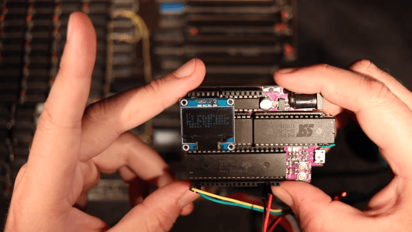
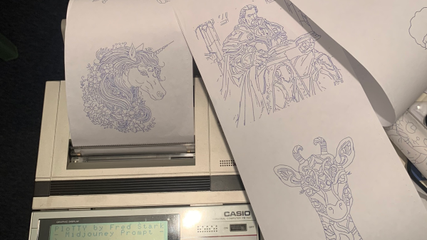
[Fred] has a Casio PB-700 pocket calculator / computer, complete with the companion docking station featuring a four-color pen plotter, model FA-10, and a microcassette tape recorder, model CM-1. He really wanted to see what this plotter could do, but there were no demos that he could find. So despite only having one working pen, [Fred] took matters into his own hands and proceeded to make his own.
What if I made a program where I type what I want to draw and the PB-700 just draws it?
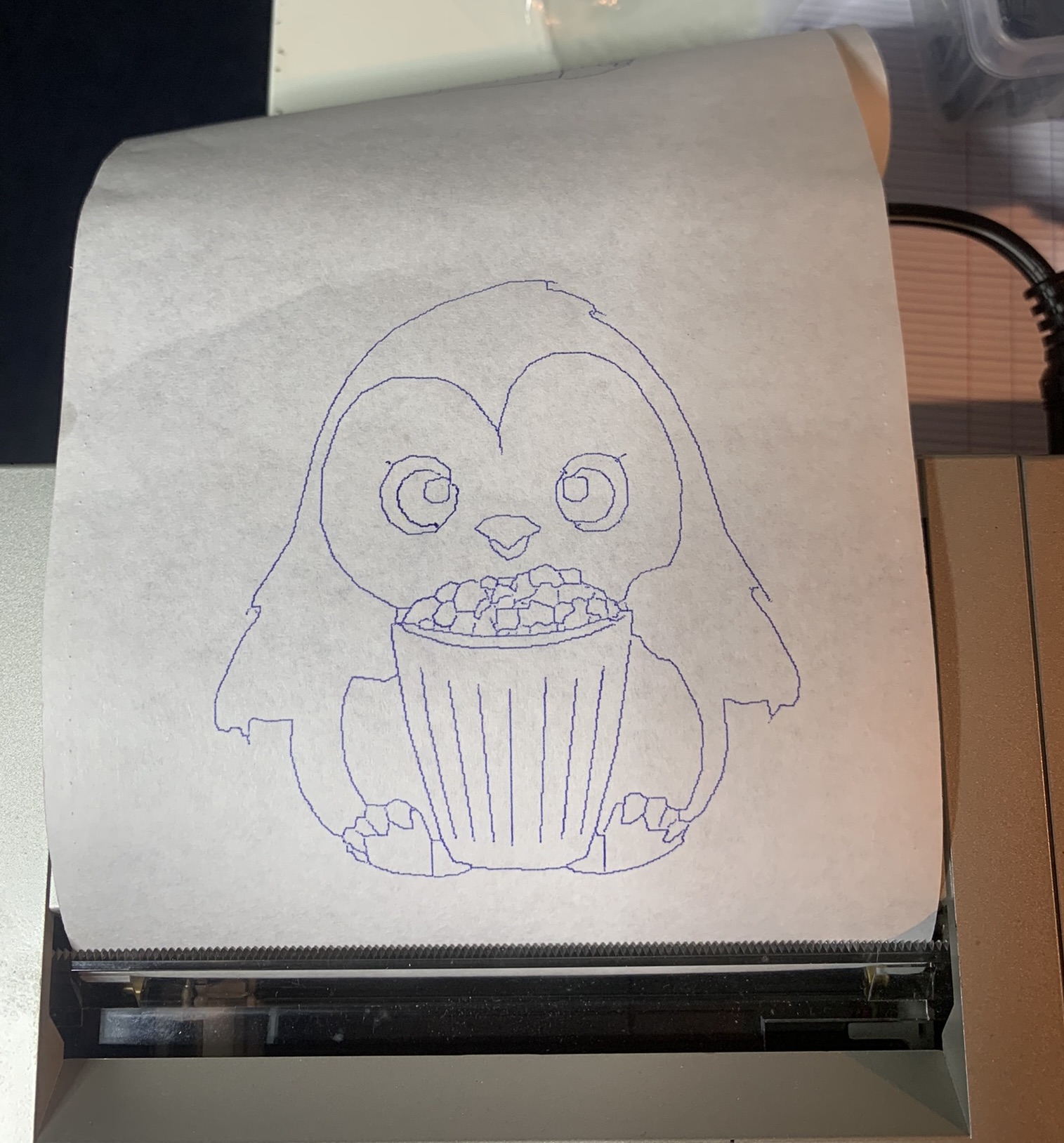
Penguin from Penguindrum eating Popcorn
[Fred] succeeds, shoehorning several sub-projects into a single convoluted work flow: request an image from the PB-700 and after a long pause the plot emerges. The cute microcassette recorder is too much of a hassle, so he emulates the audio interface on a PC using a utility called casutil that reads and writes .wav files in PB-700 format. Much of his effort is spent figuring out how to request an image from Midjourney without being banned, but eventually comes up with a workable but shaky solution. The last steps are to convert the image into a line drawing, and then wrap up all those X-Y coordinates into a Basic program and send it back down to the PB-700 for plotting.
You can read more details in the PloTTY GitHub repository. There were several of these pocket computers with plotters coming out of Japan in the 1980s. In addition to this Casio, the Radio Shack TRS-80 PC-1 and PC-2 come to mind, which were re-branded versions of the Sharp PC-1211 and PC-1500 models. We wrote about them last year. This author had a PC-2 in 1985 and used it to plot antenna patterns at his desk, bypassing the IT department’s red tape. Have you ever used any of these pocket plotters? If so, let us know in the comments below. Thanks to [Altomare] for send us the tip.