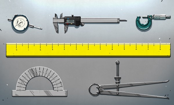
The story of precision, as told by Simon Winchester, is captured in The Perfectionists: How Precision Engineers Created the Modern World. Published in 2018, Winchester’s overview stretches as far back to the Antikythera mechanism and brings us to present day silicon wafer manufacturing. Of course, this isn’t a chronology of all-things made precisely. Instead, it’s a romp through engineering highlights that hallmark either a certain level of precision manufacturing or a particular way of thinking with repercussions for the future. Continue reading “Books You Should Read: The Perfectionists”
Reviews279 Articles
TFT35 Dual Mode 3D Print Control – Hands On
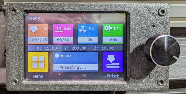
I was rebuilding one of my 3D printers — again — and decided I needed a display upgrade. A color screen is nice, but there are some limitations. I also found there are ways around these limitations, so I wanted to share my thoughts on a dual-mode color touch screen LCD controller for your 3D printer. The screen in question is a TFT35 from BigTree Tech. It is similar to an MKS screen, but it can operate in two different modes, as you will see.

A few years ago, I picked up an Anet A8 which was very inexpensive, especially on sale. Not the best printer, though, because it has that cheap acrylic frame. No problem. A box full of aluminum extrusion later, the printer was reborn. Over time, I’ve completely reworked the extrusion system and the Y-axis, leaving only the motors, bearings, and the controller/display as the original.
That last part was what bothered me. The Anet board is actually pretty capable for a small cheap board. But it is just what the printer needs and nothing more. If you wanted to hack the printer there was very little memory left and only one spare pin for I/O. So it was time to replace the board and why not the controller, too?
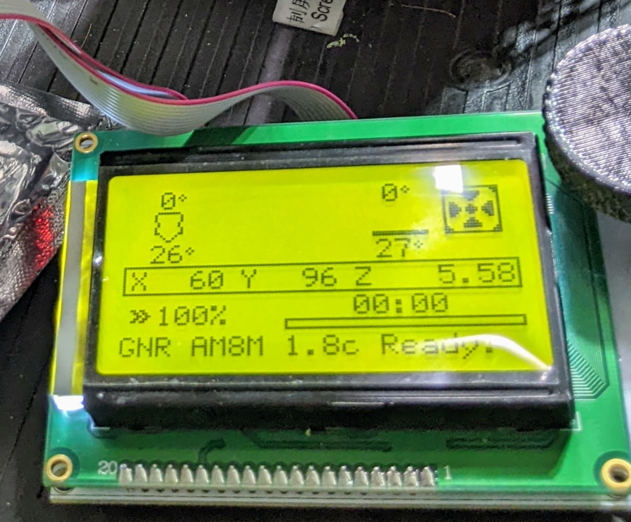
The A8 has an LCD2004. That means it has a 20×4 LCD. Instead of an encoder knob, there are five buttons: basically up, down, left, right, and enter. Most printers now have an LCD12864 which, as you can probably guess, is a 128×64 LCD and they use an encoder knob for direction that you can push for the enter key.
Continue reading “TFT35 Dual Mode 3D Print Control – Hands On”
Ham Radio SSB Transceiver Fits In Pocket
Talking about this Chinese ham radio transceiver requires a veritable flurry of acronyms: HF, SSB, QRP, and SDR to start with. [Paul] does a nice job of unboxing the rig and checking it out. The radio is a clone of a German project and provides a low-power radio with a rechargeable battery. You can see his video about the gear below.
SSB is an odd choice for low power operation, although we wonder if you couldn’t feed digital data in using a mode like PSK31 that has good performance at low power. There are several variations of the radio available and they cost generally less than $200 — sometimes quite a bit less.
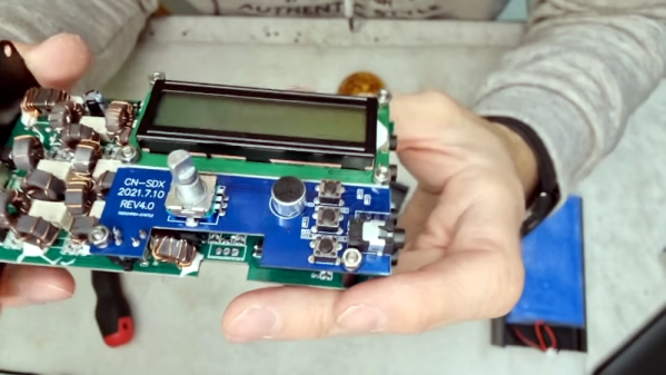
There isn’t much on the front of the radio. There are a few buttons, a rotary encoder, and an LCD along with a speaker and microphone built-in. There are ports for power to run the radio if you want to not use the battery and a separate port for battery charging. There are also ports for a key, external microphone and speakers, and audio connections that look like they’d work for digital modes. According to commenters, the radio doesn’t have an internal charging circuit, so you have to be careful what you plug into the charging port.
Looking inside, the radio looks surprisingly well made. Towards the end of the video, you can see the radio make some contacts, too. Looks like fun. This is a bit pricey for [Dan Maloney’s] $50 Ham series, but not by much. You might borrow an antenna idea from him, at least. If you prefer something more analog, grab seven transistors and build this SSB transceiver.
Multimeters Go Big Screen
We’ve noticed lately that some cheap meters have gone to having big colorful screens. The screens aren’t dot matrix, but still have lots of graphics that could be useful or could be distracting eye candy, depending. The really cheap ones seem more like a gimmick, but [OM0ET] took a look at one that looked like a fair midrange instrument with some useful display features, the GVDA GD128.
A lot of the display shows the current function of the meter. No need for an expensive multiposition switch or rows of interlocking pushbuttons. Many of these new meters also have non-contact voltage sensors, which is handy. Otherwise, it looks like a pretty conventional cheap meter. Continue reading “Multimeters Go Big Screen”
Building The DIY HP41C: A Field Report
I have a confession to make. I write about a lot of projects for Hackaday, but there are very few I read about and then go actually build a copy of it. I don’t have a lot of time and I’m usually too busy building my own stuff. But once in a while, something strikes my fancy and I’ll either raid the junk box or buy the kit. The most recent case of that was the PX-41C, a replica of the classic HP-41C.

The HP-41C is a somewhat legendary reverse-polish notation calculator. I still have my original HP-41C from 1979 (a very low serial number). It is still a workhorse but at 43 years old or so, I don’t like to leave it hanging around or near anything that might damage it. It has enough wear from the daily use it received 40 years ago. Sure, I have great emulation on my phone and I use that too, but the PX-41C kit looked fun, and with all through-hole parts it would be a quick build. The black Friday sale on Tindie sealed the deal for me.
Start-Up
The kit arrived on the Saturday after Thanksgiving, I decided to tackle it while waiting for some 3D prints. The components were all nicely bagged and marked. Tearing into the bags was a bit frustrating, but not hard and it did keep everything separate. There was a bill of materials, but — I thought — no instructions. Turns out the last part of the bill of materials is a link to some instructions. They aren’t much and I didn’t realize they were until after completing the board, but it isn’t hard to figure out. All the parts are marked on the silkscreen and you can probably figure it out — with a few caveats.
Designing Electronics That Work
[Hunter Scott] who has graced these pages a fair few times, has been working on electronics startups for the past ten years or so, and has picked up a fair bit of experience with designing and building hardware. Those of us in this business seem to learn the same lessons, quite often the hard way; we call it experience. Wouldn’t it be nice to get up that learning curve a little quicker, get our hardware out there working sooner with less pain, due to not falling into the same old traps those before us already know about? The problem with the less experienced engineer is not their lack of talent, how quickly they can learn, nor how much work they can get done in a day, but simply that they don’t know what they don’t know. There’s no shame in that, it’s just a fact of life. [Hunter] presents for us, the Guide to Designing Electronics that Work.
The book starts at the beginning. The beginning of the engineering process that is; requirements capturing, specifications, test planning and schedule prediction. This part is hard to do right, and this is where the real experience shows. The next section moves onto component selection and prototyping advice, with some great practical advice to sidestep some annoying production issues. Next there’s the obvious section on schematic and layout with plenty of handy tips to help you to that all important final layout. Do not underestimate how hard this latter part is, there is plenty of difficulty in getting a good performing, minimal sized layout, especially if RF applications are involved.
The last few sections cover costing, fabrication and testing. These are difficult topics to learn, if up till now all you’ve done is build prototypes and one-offs. These are the areas where many a kickstarter engineer has fallen flat.
Designing Electronics That Work doesn’t profess to be totally complete, nor have the answer to everything, but as the basis for deeper learning and getting the young engineer on their way to a manufacturable product, it is a very good starting point in our opinion.
The book has been around a little while, and the latest version is available for download right now, on a pay what-you-want basis, so give it a read and you might learn a thing or two, we’re pretty confident it won’t be time wasted!
The Pi Zero 2 W Is The Most Efficient Pi
Last week we saw the announcement of the new Raspberry Pi Zero 2 W, which is basically an improved quad-core version of the Pi Zero — more comparable in speed to the Pi 3B+, but in the smaller Zero form factor. One remarkable aspect of the board is the Raspberry-designed RP3A0 system-in-package, which includes the four CPUs and 512 MB of RAM all on the same chip. While 512 MB of memory is not extravagant by today’s standards, it’s workable. But this custom chip has a secret: it lets the board run on reasonably low power.
When you’re using a Pi Zero, odds are that you’re making a small project, and maybe even one that’s going to run on batteries. The old Pi Zero was great for these self-contained, probably headless, embedded projects: sipping the milliamps slowly. But the cost was significantly slower computation than its bigger brothers. That’s the gap that the Pi Zero 2 W is trying to fill. Can it pull this trick off? Can it run faster, without burning up the batteries? Raspberry Pi sent Hackaday a review unit that I’ve been running through the paces all weekend. We’ll see some benchmarks, measure the power consumption, and find out how the new board does.
The answer turns out to be a qualified “yes”. If you look at mixed CPU-and-memory tasks, the extra efficiency of the RP3A0 lets the Pi Zero 2 W run faster per watt than any of the other Raspberry boards we tested. Most of the time, it runs almost like a Raspberry Pi 3B+, but uses significantly less power.
Along the way, we found some interesting patterns in Raspberry Pi power usage. Indeed, the clickbait title for this article could be “We Soldered a Resistor Inline with Raspberry Pis, and You Won’t Believe What Happened Next”, only that wouldn’t really be clickbait. How many milliamps do you think a Raspberry Pi 4B draws, when it’s shut down? You’re not going to believe it.