Self-Solving Rubik’s Cube

Rubik’s Cube has been around for what seems like forever now, and has spawned an entire subculture devoted to solving the puzzle with automation. Most Rubik robots put the cube in a specially designed cradle bristling with actuators and sensors, and while those rigs are impressive, they don’t come close to this robotic Rubik solver built into the cube itself.

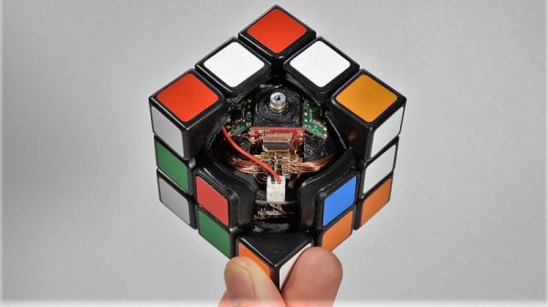
Fair warning that [Human Controller] doesn’t provide much detail on this build other than pictures; even translating the Japanese web page doesn’t offer much more information. But there are pictures, plus the video below, which reveal the engineering masterpiece encased within the standard sized Rubik’s cube. The internal mechanism of the original cube had been replaced by a spherical assembly around which the cube’s faces rotate. The sphere, which appears to be 3D-printed, houses six motors and gear trains, along with a microcontroller board and what appear to be Hall sensor boards to detect the position of each face. Everything is wired up with magnet wire to keep bundles to a minimum size, and buried deep inside is a LiPo battery pack. A disassembly video offers further clues to this ingenious device’s inner workings.

Once the cube senses that it has been scrambled, it sets to work on the solution, walking all over the table in the process. It’s clearly not just recording the scrambling steps and playing them back in reverse; the video below shows far more moves to solve the cube than the 15 it took to scramble it.

While we’re always impressed by marvels of speed like this robot with a 637 millisecond solve time, putting everything needed to solve the cube inside it is a feat worth celebrating. Here’s hoping that a build log shows up soon to satisfy our need for details.

Continue reading “Self-Solving Rubik’s Cube”

A Rotary Axis CNC Machine

There’s a certain class of parts that just can’t be made on a standard 3-axis mill, nor with a 3D printer or a lathe. These parts — weird screws, camshafts, strange gears, or simply a shaft with a keyway (or two) — can really only be made with a rotary axis on a CNC machine. Sure, you could buy a rotary axis for a Haas or Tormach for thousands of dollars, or you could build your own. That’s exactly what [Adam Zeloof] and [Matt Martone] did with their project at this year’s World Maker Faire in New York. It’s the Rotomill, a simple three-axis CNC machine, with a rotary axis, that just about anyone can build.

The design of the Rotomill uses a standard, off-the-shelf Makita rotary tool for the spindle, and uses leadscrews to move the X and Z axes around with NEMA 24 stepper motors. The A axis — the rotary bit — is driven through a worm gear, also powered by a NEMA 24. Right now this provides more than enough power to cut foam, plastic, and wood, and should be enough to cut aluminum. That last feat is as yet untested, but the design is open enough that a much more powerful spindle could be attached.

The software for this machine is a bit weird. For most CNC machines with a rotary axis, the A axis is treated as such — a rotary axis. For the Rotomill, [Adam] and [Matt] are generating G Code like it’s a normal Cartesian machine, only with one axis ‘wrapped’ around itself. This is all done through Autodesk HSM, and a properly configured Arduino running GRBL makes sense of all this arcane geometry.

It’s a great looking machine, and the guys behind it say it’s significantly less expensive than any other machine with a rotary axis. That’s to be expected, as it’s basically a five axis mill with two axes removed. Still, this entire project was built for about $2000, and some enterprising salvage and hacking could bring that price down a bit.

Planned Obsolescence Isn’t A Thing, But It Is Your Fault

The common belief is that big companies are out to get the little people by making products that break after a short period, or with substantially new features or accessories that make previous models obsolete, requiring the user to purchase a new model. This conspiracy theory isn’t true; there’s a perfectly good explanation for this phenomenon, and it was caused by the consumers, not the manufacturers.

When we buy the hottest, shiniest, smallest, and cheapest new thing we join the wave of consumer demand that is the cause of what often gets labelled as “Planned Obsolescence”. In truth, we’re all to blame for the signals our buying habits send to manufacturers. Dig in and get your flamewar fingers fired up.

Continue reading “Planned Obsolescence Isn’t A Thing, But It Is Your Fault”

World’s Smallest LED Blinky

[Mike Harrison] is known for incredibly tiny soldering. Now he’s claiming a “world’s smallest” in the form of a stand-alone LED blinker, and we think he’s got the record.

He brought it along with him to Friday’s Beagleboard Bring-a-Hack, and we got a close look at the diminutive assembly. The project was dreamed up when [Mike] saw an announcement from Seiko about a new supercapacitor in a tiny package (likely the CPH3225A giving the blinky a footprint of 3.2 x 2.5 mm). With that in hand he added a PIC 10f322 microcontroller in a SOT23 package, an 0603 smoothing capacitor, and an SMD LED.

With such a tiny package, the trickiest part is figuring out how to charge that supercap. [Mike] used a drill and hand files to make a square hole in a CR2032 battery holder to serve as a jig. The bottom of the supercap rests against the battery as a pogo pin makes the second connection to a terminal on the side of his assembly. It charges quickly and will happily blink away for about six minutes after charging.

Mike set out to make two of these, but dropped the second supercap when at his workbench to be forever lost in the detritus common to every electronics workshop. When he first pulled it out at the meetup we were on a rooftop terrace and we were more than a bit concerned that this would just blow away. How do you begin to fabricate such a tiny assembly? He used UV cured epoxy to glue them together first, then somehow completed the soldering by hand!

Continue reading “World’s Smallest LED Blinky”

DIY Arduino Soldering Iron Hits Version 2.0

A few months ago we brought word that [Electronoobs] was working on his own open source alternative to pocket-sized temperature controlled soldering irons like the TS100. Powered by the ATMega328p microcontroller and utilizing a 3D printed enclosure, his version could be built for as little as $15 USD depending on where you sourced your parts from. But by his own admission, the design was held back by the quality of the $5 replacement soldering iron tips he designed it around. As the saying goes, you get what you pay for.

But [Electronoobs] is back with the second version of his DIY portable soldering iron, and this time it’s using the vastly superior HAKKO T12 style tip. As this tip has the thermocouple and heating element in series it involved a fairly extensive redesign of the entire project, but in the end it’s worth it. After all, a soldering iron is really only as good as its tip to begin with.

This version of the iron deletes the MAX6675 used in V1, and replaces it with a LM358 operational amplifier to read the thermocouple in the T12 tip. [Electronoobs] then used an external thermocouple to compare the LM358’s output to the actual temperature at the tip. With this data he created a function which will return tip temperature from the analog voltage.

While the physical and electrical elements of the tip changed substantially, a lot of the design is still the same from the first version. In addition to the ATMega328p microcontroller, version 2.0 of the iron still uses the same 128×32 I2C OLED display, MOSFET, and 5V buck converter from the original iron. That said, [Electronoobs] is already considering a third revision that will make the iron even smaller by replacing the MOSFET and buck converter. It might be best to consider this an intermediate step before the DIY iron takes on its final form, which we’re very interested in seeing.

The first version of the DIY Arduino soldering iron garnered quite a bit of attention, so it seems there’s a decent number of you out there who aren’t content with just plunking down the cash for the TS100.

Continue reading “DIY Arduino Soldering Iron Hits Version 2.0”

One Man’s Disenchantment With The World Of Software

There is a widely derided quote attributed to [Bill Gates], that “640k should be enough for anyone”. Meaning of course that the 640 kb memory limit for the original IBM PC of the early 1980s should be plenty for the software of the day, and there was no need at the time for memory expansions or upgrades. Coupled with the man whose company then spent the next few decades dominating the software industry with ever more demanding products that required successive generations of ever more powerful PCs, it was the source of much 1990s-era dark IT humour.

XKCD no. 303 (CC BY-NC 2.5)

In 2018 we have unimaginably powerful computers, but to a large extent most of us do surprisingly similar work with them that we did ten, twenty, or even thirty years ago. Web browsers may have morphed from hypertext layout formatting to complete virtual computing environments, but a word processor, a text editor, or an image editor would be very recognisable to our former selves. If we arrived in a time machine from 1987 though we’d be shocked at how bloated and slow those equivalent applications are on what would seem to us like supercomputers.

[Nikita Prokopov] has written an extremely pithy essay on this subject in which he asks why it is that if a DOS 286 could run a fast and nimble text editor, the 2018 text editor requires hundreds of megabytes to run and is noticeably slow. Smug vi-on-hand-rolled GNU/Linux users will be queuing up to rub their hands in glee in the comments, but though Windows may spring to mind for most examples there is no mainstream platform that is immune. Web applications come under particular scorn, with single pages having more bloat than the entirety of Windows 95, and flagship applications that routinely throw continuous Javascript errors being the norm. He ends with a manifesto, urging developers to do better, and engineers to call it out where necessary.

If you’ve ever railed at bloatware and simply at poor quality software in general, then [Nikita]’s rant is for you. We suspect he will be preaching to the converted.

Windows error screen: Oops4321 [CC BY-SA 4.0]

Maker Faire NY: Programmable Air

At this year’s World Maker Faire in New York City we’re astonished and proud to run into some of the best projects that are currently in the running for the Hackaday Prize. One of these is Programmable Air, from [Amitabh], and it’s the solution to pneumatics and pressure sensing in Maker and IoT devices.

The idea behind Programmable Air is to create the cheapest, most hacker-friendly system for dealing with inflatable and vacuum-based robotics. Yes, pneumatic robotics might sound weird, but there’s plenty of projects that could make use of a system like this. The Glaucus is one of the greatest soft robotic projects we’ve ever seen, and it turns a bit of silicone into a quadruped robot with no moving parts. The only control you have over this robot is inflating one side or the other while watching this silicone slug slowly crawl forward. This same sort of system can be expanded to a silicone robot tentacle, too.

On display at the Programmable Air booth were three examples of how this device could be used. The first was a simple pressure sensor — a weird silicone pig with some tubing coming out of the nostrils was connected to the Programmable Air module. Squeeze the pig, and some RGB LEDs light up. The second demo was a balloon inflating and deflating automatically. The third demo was a ‘jamming gripper’, basically a balloon filled with rice or coffee grounds, connected to a pump. If you take this balloon, jam it onto an odd-shaped object and suck the air out, it becomes a gripper for a robotic arm. All of these are possible with Programmable Air.

Right now, [Amitabh] has just finalized the design and is getting ready to move into mass production. You can get some updates for this really novel air-powered robotics platform over on the main website, or check out the project over on Hackaday.io.