You want to put your credit card number into a web site. You know to look for a secure web site. But what does that really prove? And now that so many electronic projects have Web servers (ok, I’ll say it… the Internet of Things), do you need to secure your web server?
There was a time when getting a secure certificate (at least one that was meaningful) cost a pretty penny. However, a new initiative backed by some major players (like Cisco, Google, Mozilla, and many others) wants to give you a free SSL certificate. One reason they can afford to do this is they have automated the verification process so the cost to provide a certificate is very low.
What do you do, when you want an ohm? What is an ohm, for that matter? Take a wander over to the textbook definitions, and you’re soon deep in a world of coulombs and parallel infinite planes one meter apart in a vacuum that you probably only half remember from your high school physics class. It’s hard work, this metrology lark.
Of course, you can just order a resistor. A few cents each when you’re buying small quantities or much less when you’re buying a reel of five thousand, and there you have it. An ohm. Only it’s not really an ohm, more like nearly an ohm. Within 1% of an ohm is pretty good, but Vishay or Bourns or whoever don’t have the margins to get philosophical about those infinite planes when you’re only giving them a few cents.
When you REALLY want an ohm, you buy a standard resistor, and you pay a more significant sum. You’re never going to wire one of these up to bias a transistor or drive an LED, instead it’s about as close as it’s possible to get on your bench to the value it says on the box and you can use it for calibration purposes. PPM figures well in excess of the resolution of even superior DMMs sound pretty good to us!
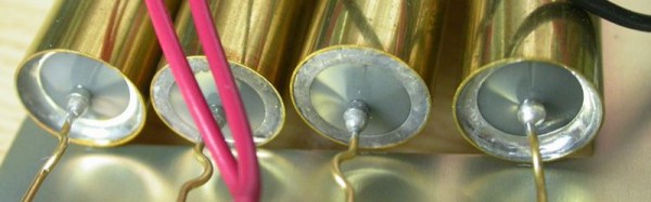
Inside he finds hermetically sealed wire-wound resistors, some oil-filled wire-wound resistors, and the occasional hefty piece of manganin. He also tears down some of the hermetically sealed resistors themselves, finding both wire-wound and foil resistance elements within.
A few years ago [Tweepy], one of the Hackaday readership’s global band of pancake enthusiasts, took possession of an aged “Self-Crêpe” machine. Judging by the look of the date codes on the ICs in the early 1980s, this machine cooked and sold a fresh crêpe on the insertion of a 1 Franc coin (about 17 U.S. cents in those days) for about thirty years.
Sadly, it would no longer produce crêpes. The aged control logic was the culprit, and rather than debug it [Tweepy] decided to replace it with a microcontroller (French language, Google Translate link). The one he chose (marked “RSF2127″, can anyone identify it?) came in a QFP package, so attaching it to a 0.1” prototyping board required some soldering wizardry with fine wires, but it was soon up and running. Some track-cutting and wiring into the original PCB, and the custom C code was ready to go.
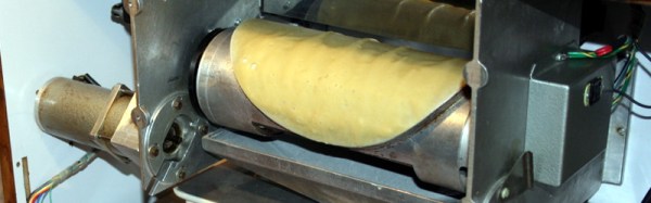
The crêpe-making part of the machine features a heated roller not unlike the one in our recently featured South African endless pancake machine in whose comment thread [Tweepy] mentioned it, but appears to use only a single-sided cooking process. The roller has a round crêpe-sized raised area. To start the cooking process, a loading bath of batter is brought up under the roller which is then rotated so that the round raised area passes through the surface of the batter. As the roller turns, it cooks the crêpe, which is then diverted from the roller to the output chute. The whole process relies on a reservoir of pre-made batter, sadly it’s not a crêpe replicator. On the other hand, a single crêpe takes about 40 seconds to create, and the machine can produce them on a continuous basis as long as you keep it stocked with batter.
We like the crêpes, we like the machine, and we like what [Tweepy] has done with it. If any of these machines made it beyond the borders of France, we’ve never seen one in our corners of the Anglophone world. This is a shame, for who wouldn’t want one of those next to the kettle and microwave oven in their hackspace! They would have needed to work on that name, though, for the English-speaking market.
If you are lucky enough to encounter a piece of homebrew electronics from the 1950s, the chances are that under the covers the components will be assembled on solder tags, each component with long leads, and chassis-mounted sockets for tubes. Easy to assemble with the most agricultural of soldering irons.
Open up a home build from the 1960s or early 1970s, and you might find the same passive components alongside germanium transistors mounted through holes in a curious widely spaced stripboard or even a home-made PCB with chunky wide tracks.
Solder tags aplenty in a commercial transmitter from the early 1960s
Cutting-edge 1970s homebrew
By the late 1970s and early 1980s you would find a more familiar sight. Dual-in-line ICs through-hole on 0.1″ spaced stripboard, and home-made PCBs starting to appear on fibreglass board. Easy to use, easy to solder. Familiar. Safe. Exactly what you’ll see on your breadboard nearly forty years later, and still what you’ll see from a lot of kit manufacturers.
But we all know that progress in the world of electronic components has not stood still. Surface-mount components have a history going back to the 1960s, and started to appear in consumer equipment from the end of the 1980s. More components per square inch, smaller, cheaper devices. Nowadays they are ubiquitous, and increasingly these new components are not offered in through-hole versions. Not a problem if your experiments are limited to the 741 and the 555, but something that rather cramps your style if your tastes extend to novel sensors for a microcontroller, or RF work.
This development has elicited a range of reactions. Many people have embraced the newer medium with pleasure, and the Hackaday.io project pages are full of really clever SMD projects as a result. But a significant number have not been able to make the jump to SMD, maybe they are put off by the smaller size of SMD components, the special tools they might require, or even the new skills they’d have to learn. When you sell a kit with SMD components these are the reactions you will hear from people who like the kit but wish it was available in through-hole, so this article is for them. To demystify working with SMDs, and to demonstrate that SMD work should be within the grasp of almost anyone who can wield a soldering iron.
But They’re So Tiny!
Tiny SMDs – fortunately most of which you will not have to worry about.
It’s likely to be the first reaction from a lifelong through-hole solderer. SMD parts are often very small indeed, and even those with larger packages can have leads that seem as numerous and thin as the hairs on a cat when seen with the rabbit-in-the-headlights panic of the uninitiated.
But it is important to take a step back and understand that not all SMDs are created equal. Some of them are grain-of-sand tiny and only hand-solderable by those with God-like powers, but plenty of devices are available in SMD packages large enough for mere mortals.
So don’t worry when you look at a board covered with grain-of-dust-sized components. Very few people could attempt that level of construction, your scribe certainly can’t. (We await commenters claiming to routinely hand-solder thousand-pin BGAs and 01005 chip components with anticipation, however such claims are useless without proof.)
Instead, concentrate on the SMD packages you can handle. SMD chip component packages are refered to by a number that relates to their dimension. Confusingly there are both metric and imperial versions of the scheme, but the format is the same: length followed by width.
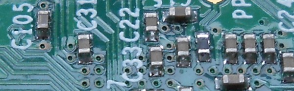
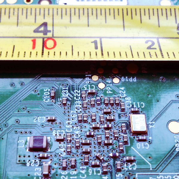
Consider the picture above with the PCB and the tape measure, it’s the underside of a Raspberry Pi model B+, and will have been assembled by a robotic pick-and-place machine. The majority of the components are very tiny indeed, but you will notice L3 as the black component towards the bottom left that looks huge compared to its neighbours. That package is a “1008”, 0.1 inches long by 0.08 inches wide. It’s still tiny, but imagine picking it up with a pair of tweezers under a magnifying glass. Not so bad, is it. You’ve probably handled plenty of things in that size range before, do SMD parts seem so scary now? The larger components – 0805, 1008, and 1206 – are surprisingly within the grasp of the average maker.
But I need all sorts of special tools!
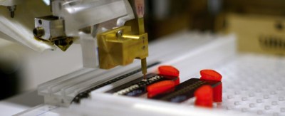
Retro Populator, a homebrew pick-and-place machine we featured back in 2014
In a commercial environment an SMD device will be assembled by machine. Glue or solder paste will be printed in the relevant parts of the board, and a robotic pick-and-place machine will retrieve components from their tape packaging and automatically place them in their correct orientations. The board will then be soldered all-at once, either in a reflow oven or by a wave soldering machine.
You’ll also see all manner of commercial kit aimed at the bench-top SMD constructor. Hot air soldering stations or SMD bits for conventional irons, all of which are very useful but come with a hefty price tag.
The good news is that you don’t need any of these special tools to dip your toe into the SMD water. You almost certainly already have everything you need, and if you don’t then very little of what you lack is specifically for SMD work. If you have the following items then you are good to go:
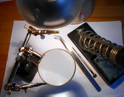
A basic SMD soldering toolkit
A good light source. Even the larger SMDs are still pretty small. Plenty of light ensures you will be able to see them clearly. A good downward pointing desk lamp should suffice. A clear high-contrast surface. Because SMDs can be difficult to see, it helps if they are manipulated over a bright white surface. A fresh sheet of white printer paper on a desk makes a suitable working area. Good hands-free magnification. Unless you are fortunate enough to have amazing eyesight, you will need a decent magnifier to work with surface-mount components. The “Helping hands” type on a stand are suitable. A very small flat-blade screwdriver. You will need this to hold surface-mount components down while you solder them. A good-quality set of precision metal tweezers. You will need these for picking up, manipulating, and turning over surface-mount devices. A fine-tipped soldering iron. If you have a standard fine tipped iron suitable for use with conventional 0.1” pitch through-hole components then you should be well-equipped.
That said there is one special tool that might be worth your consideration. Holding an SMD device while soldering it can sometimes seem like a task that needs three hands, so one or two tools can be found to help. Fortunately this is something you can build yourself. Take a look at the SMD Beak, a weighted arm for example, or your scribe’s spring clamp third hand.
I’m sorry, this is just beyond my soldering skill level
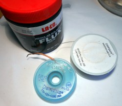
Desolder braid and plenty of flux are your friends.
It is easy to imagine when you are looking at an SMD integrated circuit that its pins are just too small and too close together, you couldn’t possibly solder them by hand. The answer is that of course you can, you simply need to view how you solder them in a different way.
With a through-hole IC you solder each 0.1″ pitch pin individually. It is something of a disaster if you manage to put a solder bridge between two pins, and you race for your desolder pump or braid.
With a surface-mount IC by comparison there is little chance that you as a mere mortal could solder each pin individually, so you don’t even try. Instead you solder an entire row at once with an excess of solder, and remove the resulting huge solder bridge with desolder braid to leave a very tidy and professional-looking job. Surface tension and plenty of flux are your friends, and there is very little soldering skill required that you do not already have if you are an experienced through-hole solderer.
If you can hold it down onto the board and see it clearly with your magnifier if necessary, then it doesn’t matter what the component is, you can solder it. Give it a try, you’ll surprise yourself!
What next?
1206 chip discrete components hand-soldered to a PCB
So we hope we’ve convinced you as an SMD doubter, that you have the ability to work with SMDs yourself. What next?
But there is no substitute for practice. Find a scrap board populated with reasonably-sized surface-mount components, and have a go at reworking it. Desoldering its components may be a bit difficult, but you should easily be able to rework the solder joints. Slather an integrated circuit’s pins with flux, and try running a blob of molten solder along them, then removing the excess with desolder braid. The great thing about a scrap board is that it doesn’t matter if you damage it, so you can practice these techniques to your heart’s content until you are satisfied with your new-found skill.
So you’re ready to move forward, and make your first SMD project. Well done! What you do next is up to you. Design your own circuit and get a PCB made, buy a kit, or find an SMD project you like on Hackaday.io with downloadable PCB files and order your own.
Whatever you do, be happy that you’ve conquered your SMD fears, and resolve to be first in the queue to try any new technology in the future!
I was visiting San Francisco, scratching my head for something cool to cover for Hackaday. When it hit me: this is one of the leading cities in the world for starting new companies. It’s known for its software, but with Tesla, Type A Machines, Intel, Apple, and more within an hour’s drive of the city, there’s got to be a hardware scene as well. Silicon isn’t a software product after-all. But where do you find it, and how do you get a hardware start-up going in one of the most expensive cities in the world?
That’s where hardware accelerators or incubators, whichever name they prefer, come in. One-third hackerspace, two-thirds business crash course, they help you skip a lot of the growing pains associated with starting a capital intensive thing like a hardware business. I dropped in, and they kindly gave me a few minutes of their time. I wanted to find out what a hacker could do if they felt it was time to turn those skulls into dollars. What are the requirements. What is the cost? What help does the incubator offer to the burgeoning capitalist in a hacker?
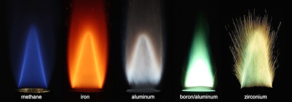
The oil age is ending. Electricity and battery power are great, but are we really going to be able to replace the entire oil industry before it’s too late? Researchers at the McGill University have come up with a possible clean fuel replacement — metal particles.
Tiny metal particles, as fine in grain size as icing sugar, have long been used for fireworks and even for rocket propellants, like the space shuttle’s solid-fuel booster rockets. But very little research has been used on applying this technology for use as a recyclable fuel — until now. Continue reading “Could Metal Particles Provide Clean Fuel For The Future?”→
I’ve worked with a lot of students who want to program computers. In particular, a lot of them want to program games. However, when they find out that after a few weeks of work they won’t be able to create the next version of Skyrim or Halo, they often get disillusioned and move on to other things. When I was a kid, if you could get a text-based Hi-Lo game running, you were a wizard, but clearly the bar is a lot higher than it used to be. Think of the “Karate Kid”–he had to do “wax on, wax off” before he could get to the cool stuff. Same goes for a lot of technical projects, programming or otherwise.
I talk to a lot of people who are interested in CPU design, and I think there’s quite a bit of the same problem here, as well. Today’s commercial CPUs are huge beasts, with sophisticated memory subsystems, instruction interpreters, and superscalar execution. That’s the Skyrim of CPU design. Maybe you should start with something simpler. Sure, you probably want to start learning Verilog or VHDL with even simpler projects. But the gulf between an FPGA PWM generator and a full-blown CPU is pretty daunting.