Did you ever see one of those videos that causes you to look at an everyday object in a new light? This is one of those videos (embedded below). And fortunately for us, there’s a write-up to go along with it in case you don’t always understand what’s going on.
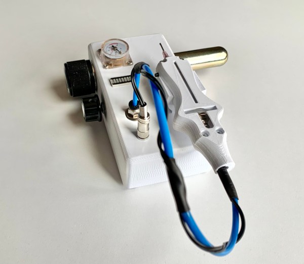
In this case, what’s going on is that [AMbros Custom] is masterfully turning a stainless steel M20 bolt into a pneumatic engraving tool. Yeah, you read that correctly. But the most amazing thing about this hack is the minimum of tools used to do it. For one thing, there’s not a lathe in sight — [AMbros Custom] just chucked it into the drill or added a few nuts and clamped it in a vise.
So, how does it work? [AMbros Custom] hooks it up to a compressor, which causes the piston inside to go up and down, agitating the engraving bit. If you don’t want to watch the video, there are a ton of build pictures in the write-up.
What else can you do with a bolt? If you have the tools, you can do plenty. You could even turn one into a secret cash stash for buying more large bolts.
Continue reading “Impressive Hack Turns Bolt Into Pneumatic Engraver”