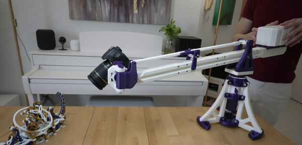
You might think the probes in the picture are just funny looking alligator clips. But if you watch [tomtektest’s] recent video, you’ll learn they are really Kelvin probes. Kelvin probes are a special type of probe for making accurate resistance measurements using four wires and, in fact, the probe’s jaws are electrically isolated from each other.
We liked [Tom’s] advice from his old instructor: you aren’t really ever measuring a resistance. You are measuring a voltage and a current. With a four-wire measurement, one pair of wires carries current to the device under test and the other pair of wires measure the voltage drop.
I’m moving, and in the process of packing all of my belongings into storage boxes to disappear into a darkened room for the next year. Perhaps I could become one of those digital nomads I hear so much about and post my Hackaday stories from a sun-kissed beach while goldfish shoals nibble at my toes. But here in a slightly damp British autumn, box after box of a lifetime’s immersion in tech needs sorting and directing. Why on earth did I hang on to three Philips N1500 VCR system video cassette recorders from the early 1970s! (Don’t worry, those have found a good home.)
Say Hello To An Old Friend Of Mine
Instantly recognisable, the AVO 8
As I was packing up my bench, I happened upon a multimeter. I have quite a few multimeters and this isn’t the first time I’ve written about these indispensable instruments, but this one’s a little special.
It’s a treasure from my youth, that most venerable of British test equipment: the AVO 8. This was the ubiquitous multimeter to be found in all manner of electrical and electronic workshops across most of the 20th century, and remains to this day one of the highest quality examples of its type.
It’s a relatively huge Bakelite box about 190mm x 170mm x 100mm in size, and it is instantly recognisable by its dual rotary selector switches and the window for viewing the needle, which forms a characteristic circular arc kidney shape.
The earliest ancestors of my meter appeared in the 1920s, and the first model 8 in the early 1950s. Mine is a Mk III that a penciled date on the inside of its meter movement tells me was made in November 1965 and which I bought reconditioned from Stewart of Reading in about 1991, but manufacture continued until the last Mk VIII rolled off the production line in 2008. It’s to my shame that my AVO is a bit dusty and that maybe I haven’t used it much of late, but as I picked it up all the memories of using it to fix dead TV sets and set up optimistic experiments in radio came flooding back. If there’s one instrument that connects me to the youthful would-be electronic engineer that I once was, then here it is. Continue reading “Ode To An AVO 8 Multimeter”→
Tired of getting his centerpunches thereabouts but not quite there, [Uri] decided something had to be done. A common tool to solve this problem is the optical centerpunch, but models on sale were just a little too pricy for something so basic. Instead, [Uri] elected to build his own.
An optical centerpunch is a simple tool that helps machinists hit a centerpunch dead on target, time after time. A guide is used that holds a clear plastic rod with a dot in the center. This dot is lined up over the spot to be centerpunched. The plastic rod is then removed and replaced with the actual punch that does the work. Not content to build something utilitarian, [Uri] instead sculpted the tool into a likeness of Sgt Pepper (of Yellow Submarine fame). Seeing the hunk of bare brass quickly become a recognisable figure on camera is a testament to [Uri’s] skill as a sculptor.
It’s a tool that can be readily built by anyone with a lathe, or, at the very least, a decent drill press. We imagine it would be particularly useful for those without perfect vision, making it easier to get punches on the mark on a regular basis. [Uri] has graced these pages before, too — he previously built an ornate tool to make all the other hammers jealous. Video after the break.
Why aluminum? [Ian] found himself reprinting previous versions’ 3D printed plastic parts multiple times due to damage in the hinged joints, or UV damage rendering them brittle. With an ingenious splaying mechanism and some sensors powered by an Arduino, [Ian] has been wearing the custom machined aluminum hand on a daily basis.
However, as with many makers, he had that itch to revisit and refine the project. Even though the last version was a big jump in quality of life, he still found room for improvement. One particular problem was that the sensors tended to shift around and made it hard to get an accurate reading. To overcome this, [Ian] turned to a molding process. However, adding a stabilizing silicon layer meant that the design of the prosthetic needed to change. With several improvements in mind, [Ian] started the process of creating the plaster positive of his palm, working to create a silicon negative. The next step from here was to create a fiberglass shell that can go over the silicone with sensor wires embedded into the fiberglass shell.
It has been amazing to see the explosion in 3D printed prosthetics over the past few years and hope the trend continues. We look forward to seeing the next steps in [Ian’s] journey towards their ideal prosthetic!
Bench power supplies are an indispensable tool when prototyping electronics. Being able to set custom voltages and having some sort of current limiting feature are key to making sure that the smoke stays inside all of the parts. Buying a modern bench supply might be a little too expensive though, and converting an ATX power supply can be janky and unreliable. Thanks to the miracle of USB-C, though, you can build your own fully-featured benchtop power supply like [Brian] did without taking up hardly any space, and for only around $12.
USB-C can be used to deliver up to 100W but is limited to a few set voltage levels. For voltages that USB-C doesn’t support, [Brian] turns to an inexpensive ZK-4KX buck-boost DC-DC converter that allows for millivolt-level precision for his supply’s output. Another key aspect of using USB-C is making sure that your power supply can correctly negotiate for the amount of power that it needs. There’s an electronic handshake that goes on over the USB connection, and without it there’s not a useful amount of power that can be delivered. This build includes a small chip for performing this negotiation as well.
With all the electronics taken care of, [Brian] houses all of this in a 3D-printed enclosure complete with a set of banana plugs. While it may not be able to provide the wattage of a modern production unit, for most smaller use cases this would work perfectly. If you already have an ATX supply around, though, you can modify [Brian]’s build using that as the supply and case too.
At first glance, you might think the piece of hardware pictured here is a modern gaming computer. It’s got water cooling, RGB LED lighting, and an ATX power supply, all of which happen to be mounted inside a flashy computer case complete with a clear window. In truth, it’s hard to see it as anything but a gaming PC.
In actuality, it’s an incredible custom electronic load that [EE for Everyone] has been developing over the last four months that’s been specifically designed to take advantage of all the cheap hardware out there intended for high-performance computers. After all, why scratch build a water cooling system or enclosure when there’s such a wide array of ready-made ones available online?
The “motherboard” with single load module installed.
Inside that fancy case is a large PCB taking the place of the original motherboard, to which four electronic load modules slot into. Each of these loads is designed to accept a standard Intel CPU cooler, be it the traditional heatsink and fan, or a water block for liquid cooling. With the current system installed [EE for Everyone] can push the individual modules up to 275 watts before the temperatures rise to unacceptable levels, though he’s hoping to push that a little higher with some future tweaks.
So what’s the end game here? Are we all expected to have a massive RGB-lit electronic load hidden under the bench? Not exactly. All of this has been part of an effort to design a highly accurate electronic load for the hobbyist which [EE for Everyone] refers to as the “Community Edition” of the project. Those smaller loads will be derived from the individual modules being used in this larger testing rig.
As a kid, one of the stories my dad told me was about mowing a fairly large field of grass on the farm with a gas-powered push mower. One day, some sort of farm tool was left in the field and the old industrial mower shredded it, sending a large piece of sharp metal hurtling toward his leg. Luckily for my dad, the large plastic wheel managed to stop the piece of metal, destroying the wheel. My grandfather was frustrated that he needed to repair the lawnmower but was grateful that my dad still had both feet attached.
Of course, this story was used as a lesson for me not to gripe about having to mow the lawn when it was my turn, but there was also the lesson that lawnmowers can be dangerous. [DuctTape Mechanic] took it upon himself to see if he could prevent that sort of accident altogether and has created an automatic safety shutdown mechanism for his family lawnmower. (Video embedded below.)
This uses an inductive sensor that can detect metal before it gets sucked into the mower itself. The sensor trips a relay which forcibly shuts the mower down by grounding the ignition coil. While it doesn’t physically stop the blade like other safety mechanisms, it does prevent a situation from escalating by turning off power to the blade as soon as possible. Getting to the ignition coil wasn’t easy as it required getting deep into the engine itself, but now [DuctTape Mechanic] has a mower that could be expanded further with things such as with a capacitive sensor or more smarts to determine if it is detecting underground or above ground metal.
Someday we’ll have robotic mowers, but until then, we laud the efforts of hackers out there trying to make the world a little safer.