The success that [Julian Baumgartner] has found on YouTube is a perfect example of all that’s weird and wonderful about the platform. His videos, which show in utterly engrossing detail the painstaking work that goes into restoring and conserving pieces of fine art, have been boosted in popularity by YouTube’s Autonomous Sensory Meridian Response (ASMR) subculture thanks to his soft spoken narration. But his latest video came as something of a surprise to lovers of oil paintings and “tingles” alike, as it revealed that he’s also more than capable of scratch building his own equipment.
Anyone who’s been following his incredible restorations will be familiar with his heated suction table, which is used to treat various maladies a canvas may be suffering from. For example, by holding it at a sufficiently high temperature for days on end, moisture can be driven out as the piece is simultaneously smoothed and flattened by the force of the vacuum. But as [Julian] explains in the video after the break, the heated suction table he’s been using up to this point had been built years ago by his late father and was starting to show its age. After a recent failure had left him temporarily without this important tool, he decided to design and build his own fault-tolerant replacement.
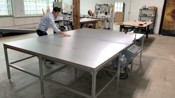
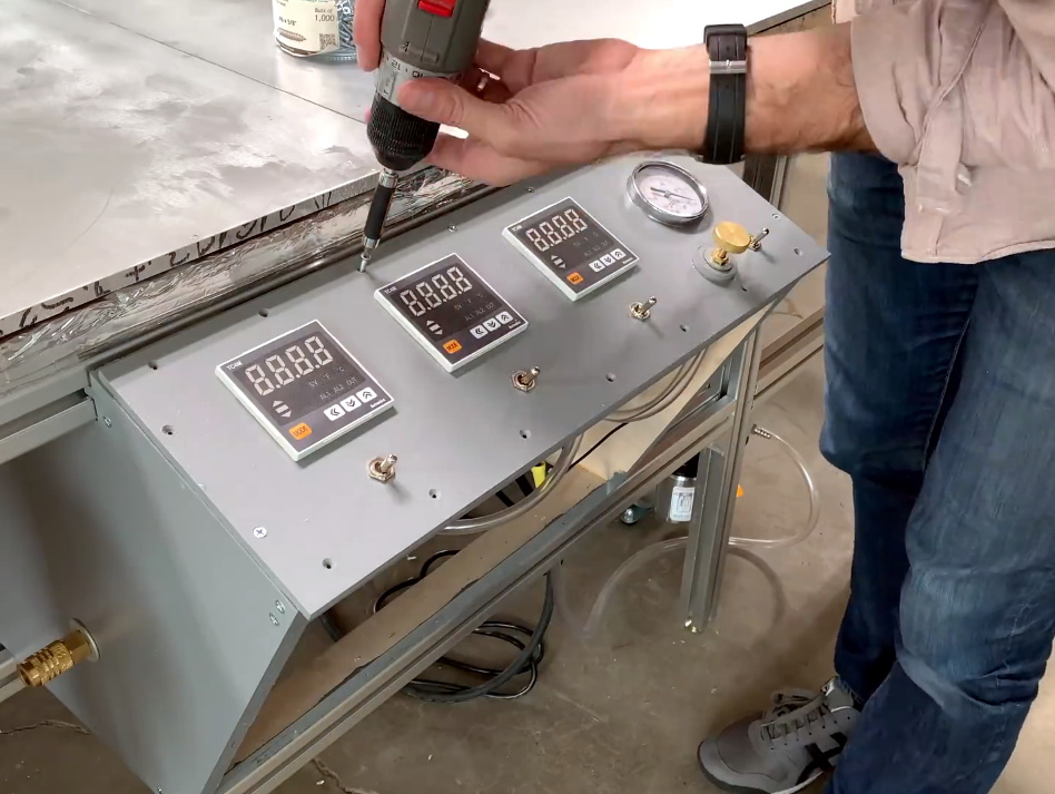
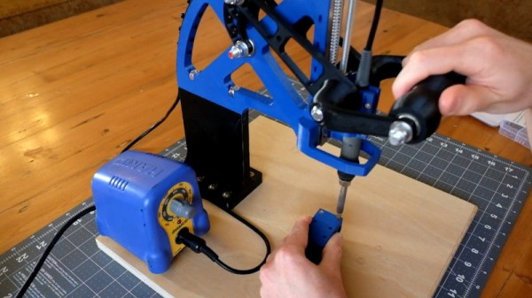
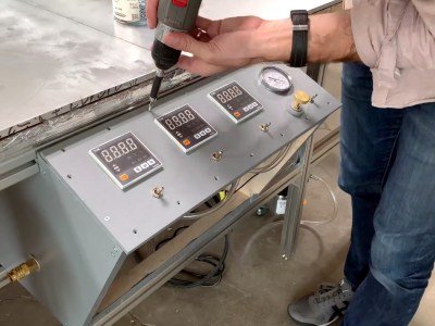 The table itself is built with a material well known to the readers of Hackaday: aluminum extrusion. As [Julian] constructs the twelve legged behemoth, he extols the many virtues of working with 4040 extrusion compared to something like wood. He then moves on to plotting out and creating the control panel for the table with the sort of zeal and attention to detail that you’d expect from a literal artist. With the skeleton of the panel complete, he then begins wiring everything up.
Underneath the table’s 10 foot long surface of 6061 aluminum are 6 silicone heat pads, each rated for 1,500 watts. These are arranged into three separate “zones” for redundancy, each powered by a Crydom CKRD2420 solid state relay connected to a Autonics TC4M-14R temperature controller. Each zone also gets its own thermocouple, which [Julian] carefully bonds to the aluminum bed with thermally conductive epoxy. Finally, a Gast 0523-V4-G588NDX vacuum pump is modified so it can be activated with the flick of a switch on the control panel.
What we like most about this project is that it’s more than just a piece of equipment that [Julian] will use in his videos. He’s also released the wiring diagram and Bill of Materials for the table on his website, which combined with the comprehensive build video, means this table can be replicated by other conservators. Whether it’s restoring the fine details on Matchbox cars or recreating woodworking tools from the 18th century, we’re always excited to see people put their heart into something they’re truly passionate about.
Continue reading “When Engineering, Fine Art, And ASMR Collide” →
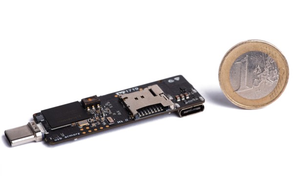
 The USB Armory Mk II is powered by an upgraded 900 MHz ARM Cortex-A7 processor, though it retains the same 512 MB of RAM from the previous version. Like the original, there’s a micro SD slot to hold the Linux operating system, but this time it’s supplemented with an onboard 16 GB eMMC chip. There’s even a physical switch that allows the user to choose which storage device they want to boot from. Other additions for the Mk II include Bluetooth connectivity, and a hardware true random number generator (TRNG).


