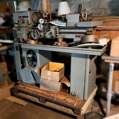
[Advoko] is an expert at milling logs into various sizes of boards. He typically uses nothing but a chainsaw to enable him to mill on-site without needing to bring any large or expensive equipment. The only problem is that sometimes he gets a little carried away running his mill non-stop until he has enough lumber for whatever project he is building, which has led to some repetitive strain injuries. To enable him to continue to run his mill, he’s created this self-propelled chainsaw jig.
The creation of the self-propelled chainsaw was a little serendipitous. [Advoko] needed to mill a tree which had fallen on a slope, and he couldn’t move the large trunk before starting to mill. To avoid fatigue while pulling his chainsaw upwards, he devised a system of rubber belts that would help pull the weight of the chainsaw up the hill. Noticing that if the chainsaw could have been operated downhill, it would essentially pull itself along the cut, he set about building a carriage for the mill to hold the chainsaw in place while it semi-autonomously milled lumber for him.
The chainsaw jig isn’t fully autonomous; [Advoko] still needs to start and stop the chainsaw and set up the jig. It does have a number of safety features to prevent damage to the jig, the chainsaw, and himself too, and over a number of iterations of this device he has perfected it to the point where he can start it on a cut and then do other tasks such as move boards or set up other logs for cutting while it is running, saving him both time and reducing his risk of other repetitive strain injuries. If you don’t fully trust the automatic chainsaw jig, take a look at this one which requires a little more human effort but still significantly reduces the strain of milling a large log.
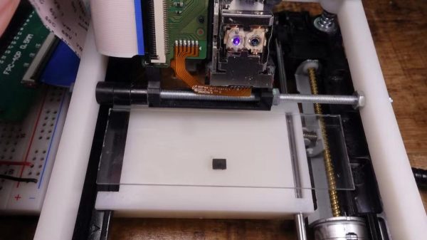
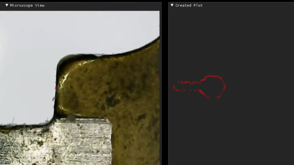
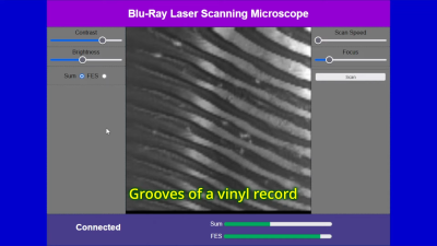 The trick is repurposing the optical pickup unit that is typically used to read optical discs. In particular, the build relies on the photodiodes that are usually used to compute focus error when tracking a disc. To turn this into a laser scanning microscope, the optical pickup is fitted to a 3D printed assembly that can slew it linearly for imaging purposes.