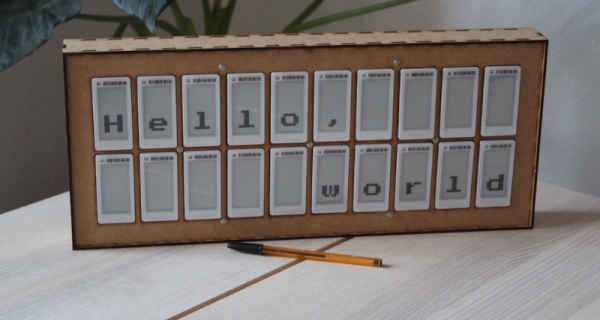
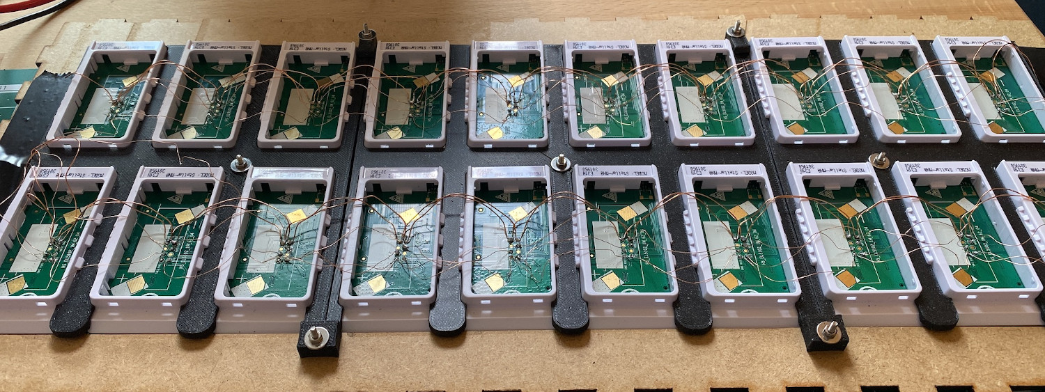
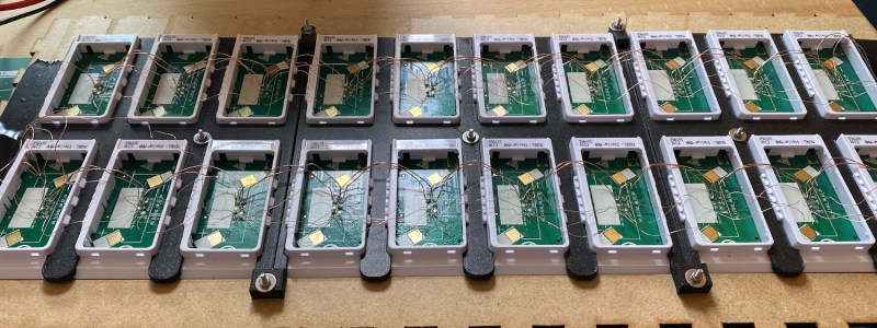
How The Flipper Zero Hacker Multitool Gets Made And Tested

Flipper Zero is an open-source multitool for hackers, and [Pavel] recently shared details on what goes into the production and testing of these devices. Each unit contains four separate PCBs, and in high-volume production it is inevitable that some boards are faulty in some way. Not all faults are identical — some are not even obvious —  but they all must be dealt with before they end up in a finished product.

One of several custom test jigs for Flipper Zero. Faults in high volume production are inevitable, and detecting them early is best.

Designing a process to effectively detect and deal with faults is a serious undertaking, one the Flipper Zero team addressed by designing a separate test station for each of the separate PCBs, allowing detection of defects as early as possible. Each board gets fitted into a custom test jig, then is subjected to an automated barrage of tests to ensure everything is as expected before being given the green light. A final test station gives a check to completed assemblies, and every test is logged into a database.

It may seem tempting to skip testing the individual boards and instead just do a single comprehensive test on finished units, but when dealing with production errors, it’s important to detect issues as early in the workflow as possible. The later a problem is detected, the more difficult and expensive it is to address. The worst possible outcome is to put a defective unit into a customer’s hands, where a issue is found only after all of the time and cost of assembly and shipping has already been spent. Another reason to detect issues early is that some faults become more difficult to address the later they are discovered. For example, a dim LED or poor antenna performance is much harder to troubleshoot when detected in a completely assembled unit, because the fault could be anywhere.

[Pavel] provides plenty of pictures and details about the production of Flipper Zero, and it’s nice to see how the project is progressing since its hyper-successful crowdfunding campaign.

Live Energy Monitor Helps Plan Power-Hungry Appliance Use

There are a lot of good reasons to have a better understanding of one’s household power use, and that is especially true for those that do their own solar power collection. For example, [Frederick] determined that it would be more efficient to use large appliances (like a dishwasher or washing machine) when there was excess solar power available, but the challenge was in accessing the right data in a convenient way. His Raspberry Pi-based live energy monitor was the solution, because it uses an LED matrix to display live energy data that can be consulted at a glance.

Interestingly, this project isn’t about hacking the power meter. What this project is really about is conveniently accessing that data when and where it is best needed. [Frederick] has a digital power and gas meter with the ability to accept a small wireless dongle. That dongle allows a mobile phone app to monitor power usage, including whether power is being taken from or exported to the grid.

Since [Frederick] didn’t want to have to constantly consult his mobile phone, a Raspberry Pi using a Pimoroni Unicorn HAT HD acts as a glanceable display. His Python script polls the power meter directly over WiFi, then creates a live display of power usage: one LED for every 250 W of power, with the top half of the display being power used, and the bottom half representing power exported to the grid. Now the decision of when to turn on which appliances for maximum efficiency is much easier, not by automating the appliances themselves, but simply by displaying data where it needs to be seen. (This kind of thing, incidentally, is exactly the idea behind the Rethink Displays challenge of the 2021 Hackaday Prize.)

As for those of us without a digital power meter that makes it easy for residents to access power data? It turns out there is no reason a power meter’s wireless service interface can’t be sniffed with RTL-SDR.

Extracting The WiFi Firmware And Putting Back A Keylogger

In the interest of simplification or abstraction, we like to think of the laptop on the kitchen table as a single discrete unit of processing. In fact, there is a surprisingly large number of small processors alongside the many cores that make up the processor. [8051enthusiast] dove into the Realtek rtl8821ae WiFi chip on his laptop and extracted the firmware. The Realtek rtl8821ae chip is a fairly standard Realtek chip as seen in this unboxing (which is where the main image comes from).

True to his name, [8051enthusiast] was pleased to find that the rtl8821ae was clearly based on the Intel 8051. The firmware was loaded on startup from a known file path and loaded onto the chip sitting in an M.2 slot. Careful consideration, [8051enthusiast] reasoned that the firmware was using RTX51 Tiny, which is a small real-time kernel.

The firmware is loaded at 0x4000 but it calls to code below that address, which means there is a ROM on the chip that contains some code. The easiest way to extract it would be to write some custom code that just copies the masked ROM back to the main CPU via the shared memory-mapped config space, but the firmware is checksummed by the masked ROM code. However, the checksum is just a 16-bit XOR. With a tweak in the kernel to allow accessing the shared config space from userspace, [8051enthusiast] was on his way to a complete firmware image.

Next, [8051enthusiast] looked at what could be done with his newfound hackability. The keyboard matrix is read by the Embedded Controller (EC), which happens to be another 8051 based microcontroller. There also happens to be an RX and a TX trace from the EC to the m.2 slot (where the rtl8821ae is). This has to do with 0x80 postcodes from the processor being routed out somewhere accessible via the EC. With a bit of custom code on both the EC and the WiFi chip, [8051enthusiast] had a keylogger that didn’t run on the main processor broadcasting the PS/2 keystrokes as UDP packets.

Of course, there are plenty of other 8051 based devices out there just waiting to be discovered. Like this 8051 based e-ink display controller.

[Main image source: Realtek RTL8821AE unboxing on YouTube by Евгений Горохов]

Inside A 20-Watt Traveling Wave Tube Amplifier From Apollo

When the Apollo astronauts made their way to the Moon, their communication equipment had a transmission power of a mere 20 W, which the sensitive receivers back on Earth managed to pick up. But this isn’t just any amplifier, it’s a Traveling Wave Tube amplifier (TWT), as [Ken Shirriff] explains in a recent article.

The most fascinating thing about these TWTs isn’t just their role during the Apollo missions, but the fact that even today this type of vacuum tube is still among the most efficient and compact types of RF amplifier. As a result today’s high-tech satellites still commonly feature these devices.

As always, [Ken] entertains and enlightens us with how the TWT and the rest of the amplifier system worked.


USB Power Bank’s Auto-Off Becomes Useful Feature In Garage Door Remote

For devices that are destined for momentary and infrequent use as well as battery power, some kind of power saving is pretty much a required feature. For example, when [PJ Allen] turned two ESP8266-based NodeMCU development boards into a replacement wireless remote garage door opener, a handy USB power bank ended up serving as a bit of a cheat when migrating the remote away from the workbench. Instead of moving the board from USB to battery power and implementing some kind of sleep mode or auto-off, [PJ Allen] simply plugged in a USB power bank and let it do all the work.

This is how the feature works: some USB power banks turn themselves off unless they detect a meaningful current draw. That means that if the power bank is charging a phone, it stays on, but if it’s only lighting up a few LEDs, it’ll turn itself off. This feature can be a frustrating one, but [PJ Allen] realized that it could actually be useful for a device like his garage door remote. Turning on the power bank delivers 5 V to the NodeMCU board and allows it to work, but after about fifteen seconds, the power bank turns itself off. Sure, strapping a power bank to the remote makes the whole thing bigger than it needs to be, but it’s a pretty clever use of the minimum load as an effortless auto-off feature.

The NodeMCU boards in [PJ Allen]’s DIY remote use ESP-NOW for their wireless communications, a nifty connectionless protocol from Espressif that we’ve seen used in other projects as well, such as this ESP32-based walkie-talkie.

QMESH: LoRa Mesh Networked Voice Communications

LoRa is great for sending short data packets over long ranges but is not normally suitable for voice communications. [Dan Fay] is looking to change this with QMesh, a synchronized, flooded mesh network protocol for ham radio applications.

In a flooded mesh network every node repeats every message it receives. This has the theoretical advantage of making the network self-healing if a single node stops working, but often just means that the nodes will interfere with each other. Thanks to some characteristics of LoRa, [Dan] is using several tricks to get around this packet collision problem. LoRa network can make use of the “capture effect”, which allows a receiver to differentiate between two packets if the power level difference is large enough. This is further improved by adding forward error correction and slightly changing the frequency and timing of the LoRa chirps. QMesh also implements TDMA (Time Division Multiple Access) by splitting transmission into time slots, and only transmitting every third slot. This means it is operating on a 33% duty cycle, which is much higher than the 0.1%-10% allowed on license-free ISM-bands, which legally limits it to the ham bands.

On the hardware side, [Dan] has been using the STM32 NUCLEO-144 development boards with F4/L4/F7/H7 microcontrollers and a custom shield with a 1 W LoRa module and OLED screen. While [Dan] wants to eventually build handheld radios, he plans to first develop small FM repeaters that encode voice as codec2 and use QMesh as a backhaul. QMesh is still under development, but we would love to see the results of some long-range testing, and we are excited to see how it matures.

If your interested in a more basic LoRa-based human-to-human messaging system, take a look at Meshtastic. It’s been going very rapidly over the past year. To learn more about LoRa and other digital modulation schemes, check out the crash course we did with an SDR a while back.

Hacking A Solar Inverter RF Interface

One of the main advantages of cheap wireless modules is that they get used in consumer electronics, so if you know what’s being used you can build your own compatible hardware. While investigating the RF interface used in a series of cheap “smart” solar inverters [Aaron Christophel], created an Arduino library to receive inverter telemetry using a $2 RF module. See the demonstration after the break.

[Aaron] bought the inverter and ~40 euro USB “Data Box” that allows the user to wirelessly monitor the status of the inverter. Upon opening the two units, he found that they used LC12S 2.4Ghz modules, which create a wireless UART link. With a bit of reverse engineering, he was able to figure out the settings for the RF modules and the serial commands required to request the status of the inverter. He doesn’t delve into the possible security implications, but there doesn’t appear to be any form of encryption in the link. It should be possible for anyone with a module to sniff the messages, extract the ID of the inverter, and hijack the link. Just knowing the status of the inverter shouldn’t be all that dangerous, but he doesn’t mention what other commands can be sent to the module. Any others could have more severe implications.

Sniffing the wireless signal flashing through the air around us is a regular topic here on Hackaday. From testing the security of WiFi networks with an ESP32 to monitoring SpaceX launches with an SDR, the possibilities are infinite.

Continue reading “Hacking A Solar Inverter RF Interface”