Over the years [Integza] has blown up or melted many types of jet engine, including the humble pulsejet. Earlier improvements revolved around pumping in more fuel, or forced air intakes, but now it’s time for a bit more refinement of the idea, and he takes a sidestep towards the more controllable detonation engine. His latest experiment (video, embedded below) attempts to dial-in the concept a little more. First he built a prototype from a set of resin printed parts, with associated tubing and gas control valves, and a long acrylic tube to send the exhaust down. Control of the butane and air injection, as well as triggering of the spark-ignition, are handled by an Arduino — although he could have just used a 555 timer — driving a few solid state relays. This provided some repeatable control of the pulse rate. This is a journey towards a very interesting engine design, known as the rotating detonation engine. This will be very interesting to see, if he can get it to work.
Detonation engines operate due to the pressure part of the general thrust equation, where the action is in the detonative combustion. Detonative combustion takes place at constant pressure, which theoretically should lead to a greater efficiency than boring old deflagration, but the risks are somewhat higher. Apparently this is tricky to achieve with a fuel/air mix, as there just isn’t enough oomph in the mixture. [Integza] did try adding a Shchelkin spiral (we call them springs around here) which acts to slow down the combustion and shorten the time taken for it to transition from deflagration to detonation.
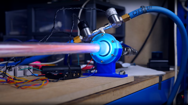
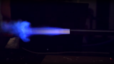
It sort of worked, but not well enough, so running with butane and pure oxygen was the way forward. This proved the basic idea worked, and the final step was to rebuild the whole thing in metal, with CNC machined end plates and some box section clamped with a few bolts. This appeared to work reasonably well at around 10 pulses/sec with some measurable thrust, but not a lot. More work to be done we think.
We hinted at earlier work on forced-air pulsejets, so here that is. Of course, whilst we’re on the subject of pulsejets, we can’t not mention [Colinfurze] and his pulsejet go kart.
Continue reading “A Detonation Engine Prototyped Using Resin Printing”