
[Billy] has a special interest in passive hydroponics (also known as the Kratky method), which is a way of growing plants in nutrient-rich water that does not circulate. As the plant grows and liquid level drops, only the tips of the roots remain submerged while more and more of the root surface is exposed to oxygen in a harmonious balance. However, “thirsty” plant types (tomatoes, for example) throw off this balance, and the system needs to be modified. To address this, [Billy] designed and printed a passive float valve system that takes care of topping up the reservoir only when needed, without using pumps or any other electrical equipment.
Commercial or industrial float valves are too big to use in his small tanks, which led [Billy] to test dozens of DIY designs. He used everything from plastic water bottles to pipe ends, but nothing quite measured up. With 3D printing, [Billy] was able to create a sealed, lightweight float that exactly matched the housing and tube locations.

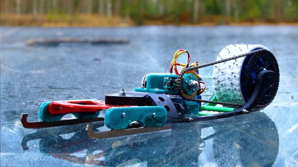
The way [Billy]’s float valve works is by using a hollow object as a kind of buoyant plug inside a housing. When the water level is high, the buoyant object rises up and presses a strip of silicone against an outlet, preventing water from flowing. If the water level is low, the buoyant plug drops and water is free to flow. With a reservoir of fresh nutrient-rich water placed above the grow tank, gravity takes care of pushing a fresh supply down a tube, so no active pump is needed. Combined with a passive float valve, the system pretty much runs itself.
Watch [Billy] give a tour of his system and valve design in the video embedded below. He’s got a lot of experience when it comes to working with projects involving liquids. Only someone as comfortable as he is would make his own DIY dishwasher.
Continue reading “DIY Float Valve For Passive Hydroponics Leverages 3D Printing”
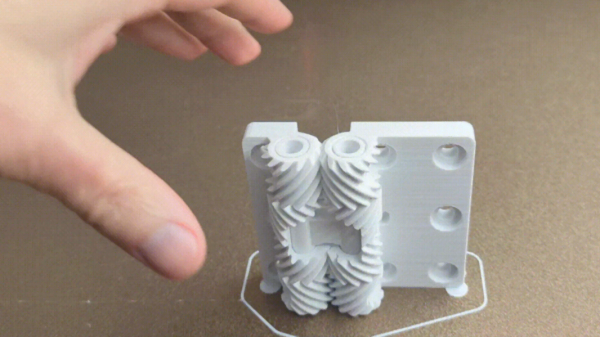
 Of course, hinges — even strong ones — are not particularly hard to find items. They’re available in a mind-boggling array of shapes and sizes. But what’s interesting about this design is that it shows what’s easily within the reach of just about any hobbyist nowadays. Not that long ago, designing and creating an object like this would not have been accessible to most home enthusiasts. Making it without a modern 3D printer would certainly have been a challenge in its own right.
![USB to Dupont adapter by [PROSCH]](https://hackaday.com/wp-content/uploads/2022/01/2022-01-01-USB-to-DuPont-adapter-feat.jpg?w=600&h=450)


