Useful Build Tips For Making LED Panel Frames

[NotLikeALeafOnTheWind] has created many LED-based display projects, and shares his method for making attractive LED panel frames and mounts. At first glance it may look as though slapping a rectangle of aluminum extrusion around a display is all it takes, there is also the mounting and management of wiring, power supply, and possibly a Raspberry Pi to deal with. The process of building an attractive frame also has a few hidden gotchas that can be avoided with a bit of careful planning.

Magnetic feet on the LED panels makes mounting much easier and more flexible.

Here is one tip that will resonate with some readers: don’t rely on specified dimensions of parts; measure the actual parts yourself. There can be small differences between what a data sheet says to expect, and the dimensions of the actual part in one’s hands. It may not be much, but it can be the difference between an ideal fit, and something that looks like a bit of a hack job.

[NotLikeALeafOnTheWind] provides some basic frame layouts, and suggests using two- or three-channel extrusions to provide a flat bezel around the display edge if desired. Mounting the LED panel itself is done with magnetic feet and providing a length of steel bar to which the display can attach. This can provide a flush mount while avoiding the whole issue of screw-mounting the display panels themselves, or sliding them into channels. For mounting all the other hardware, a piece of DIN rail and some 3D-printed parts takes care of that.

The result looks slick and sturdy, and some of the tips are sure to be useful even if the whole process isn’t applied. We like the way the basic design scales and is flexible about the thickness and size of the LED panels themselves, making it a promising way to accommodate perfectly functional oddball panels that end up in the trash.

Improving Cheap Ball Screws

Most 3D printers use leadscrews for at least one axis. These are simple devices that are essentially a steel screw thread and a brass nut that travels on it. However, for maximum precision, you’d like to use a ball screw. These are usually very expensive but have many advantages over a leadscrew. [MirageC] found cheaper ball screws but, since they were inexpensive, they had certain limitations. He designed a simple device that improves the performance of these cheap ball screws.

Superficially, a ball screw looks like a leadscrew with an odd-looking thread. However, the nut is very different. Inside the nut are ball bearings that fit in the grooves and allows the nut to spin around with much less friction. A special path collects the ball bearings and recirculates them to the other side of the nut. In general, ball screws are very durable, can handle higher loads and higher speeds, and require less maintenance. Unlike leadscrews, they are more expensive and are usually quite rigid. They are also a bit noisier, though.

Ball screws are rated C0 to C10 precision where C10 is the least accurate and the price goes up — way up — with accuracy. [MirageC] shows how cheaper ball screws can be rolled instead of precision ground. These screws are cheaper and harder, but exhibit more runout than a precision screw.

This runout caused wobble during 3D printing that was immediately obvious on the prints. Using a machinist’s dial gauge, [MirageC] found the screws were not straight at all and that even a relatively poor C7 ball screw would be more precise.

The solution? A clever arrangement of 3D printed parts. ball bearings, and magnets. The device allows the nut to move laterally without transmitting it to the print bed. It is a clever design and seems to work well.

Continue reading “Improving Cheap Ball Screws”

It’s Noodles All The Way Down: Ramen Comes To 3D Printer Support

While ramen support might sound like a help desk for soup, it is actually a technique [GeoDroidJohn] uses to get easy-to-remove support structures on 3D prints. We saw the video below and we have to admit that it did remind us of a brick of uncooked ramen noodles.

We had to dig a little further to find out how he did it. We finally found a Reddit post that gives the recipe for Simplify 3D:

  • Nozzle diameter/2= layer height
  • Support material every other layer, 15% crossing at -45, and 45
  • 5 dense layers at 90% 0 gap layers top or bottom.

We have to admit, we try to avoid support where we can, and where we can’t we just pick one of the stock Cura settings. It wasn’t entirely clear how — or even if — you could replicate this in slicers other than Simplify 3D. The layer height, of course, is a given. We think 15% support density with [-45, 45] in the “line directions” box might get partially there. Maybe someone who is an expert in Simplify and some other slicers can help translate.

In any event, it did make us think about experimenting with different support structures. We’ve played with Cura’s tree supports before this and liked them. So maybe the defaults aren’t always the best.

We’d like to have time to try more of what we read about supports. You can also fit your printer with a marker if you want to try that.

Continue reading “It’s Noodles All The Way Down: Ramen Comes To 3D Printer Support”

3D Print Your Next Antenna

Building antennas is a time-honored ham radio tradition. Shortwave antennas tend to be bulky but at VHF frequencies the antenna sizes are pretty manageable. [Fjkaan’s] 2 meter quadrifilar helicoidal antenna is a good example and the structure for it can be created with 3D printing combined with electrical conduit.

Many people, including [G4ILO] use PVC pipe for the structure, and that design inspired [Fjkaan]. Despite being a bit less substantial, the conduit seems to work well and it is easy to cut. The helical design is common for satellite work owing to its circular polarization and omnidirectional pattern.

Continue reading “3D Print Your Next Antenna”

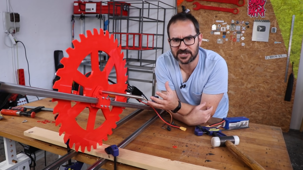
Plotter Uses Dual Disks

If you want to move a pen (or a CNC tool, or a 3D printing hot end) in the X and Y plane, your choices are typically pretty simple. Many machines use a simple cartesian XY motion using two motors and some sort of linear drive. There’s also the core-XY arrangement where two motors move belts that cause the head to travel in two directions. Delta printers use yet another arrangement, but one of the stranger methods we’ve seen is the dual disk polar printer which — as its name implies — uses two rotating disks.

The unique mechanism uses one motor to rotate a disk and another motor to rotate the entire assembly. The print head — in this case a pencil — stays stationary. as you can see in the video below.

Continue reading “Plotter Uses Dual Disks”

Custom 3D Printed Vitamins Are Just A Few Clicks Away

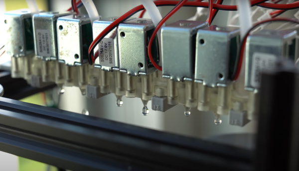
It’s recently come to our attention that a company by the name of Nourished has carved out a niche for themselves by offering made-to-order gummy vitamins produced with their own custom designed 3D printers. Customers can either select from an array of pre-configured “stacks”, or dial in their own seven layers of gelatinous goodness for a completely bespoke supplement.

Now we can’t vouch for whether or not taking a custom supplement like this is any better than just popping a traditional multi-vitamin, but we’ll admit the hardware Nourished has developed is pretty interesting. As briefly seen in the video after the break, large syringes are filled with the seven different vitamin suspensions, and then loaded into what appears to be a heated chamber for extrusion. This is not unlike other food-grade 3D printers we’ve seen, such as the Cocoa Press.

It looks like all of the syringes are being depressed simultaneously with a plate and a pair of beefy lead screws, so it seems the order in which the layers are placed down must be different for each nozzle. A blog post on the company’s site from early last year shows a wildly different machine being used to produce the vitamins, so either their core technology is changing rapidly, or perhaps the printer being used depends on whether they’re running off the customized stacks versus the standard formulations.

Interestingly, this is very similar to a concept floated by the U.S. Army’s Combat Feeding Directorate (CFD) back in 2014. They reasoned that a 3D printer could be used to produce meal bars that were customized for each soldier’s personal nutritional needs. Being largely impractical for the battlefield, the program didn’t get very far. But thanks to consumers who are willing to pay the premium that Nourished is charging for this service, it seems the idea has turned into a lucrative business model.

Continue reading “Custom 3D Printed Vitamins Are Just A Few Clicks Away”

A 3D Printed Camera Arm For Great 3D Print Timelapses

If you’re a maker that publishes projects online, you’ll be well across the production values arms race that’s been raging over the past decade. For those in the 3D printing space, this means that you’ll need to be producing slick timelapse videos of your prints. [BuildComics] is now doing just that, with a custom camera arm to help do the job. (Video, embedded below.)

The arm relies on a 3D-printed gear train that allows a stepper motor to turn it slowly throughout the print’s duration. It’s controlled by an Arduino that receives commands via Firmata. The arm is mounted on top of the printer, holding a webcam above the build plate for a good view. It’s setup via Octolapse to take images as each layer is finished, giving that haunting look of a model materialising on the print bed throughout the duration of the timelapse.

Files are available for those wishing to build their own. The design as used is for the Prusa Mini, but it should be adaptable to other printers without too much trouble. We’ve reported on Octolapse before, with its videos proving to be the gold standard when it comes to the art of the printing time lapse.

Continue reading “A 3D Printed Camera Arm For Great 3D Print Timelapses”