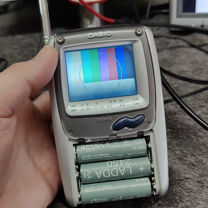
Five Oddest Op Amp Applications

You think of op amps as amplifiers because, no kidding, it is right in the name. But just like some people say, “you could do that with a 555,” [Doctor Volt] might say, “you can do that with an op amp.” In a recent video, you can see below, he looks at simulations and breadboards for five applications that aren’t traditional amplifiers.

Of course, you can split hairs. A comparator is sort of an amplifier with some very specific parameters, but it isn’t an amplifier in the classic sense.

Continue reading “Five Oddest Op Amp Applications”

A black and white slide with the Supercon 8 logo in the top left, the text, "Nanik Adnani" and "A Hacker's Guide to Analog Design in a Digital World" is in the bottom left. To the right is a circularly cropped image of An image of a college student in glasses and a cap sitting with a black camera in his lap.

Supercon 2024: A Hacker’s Guide To Analog Design In A Digital World

We often think of analog computing as a relic of the past, room-sized monstrosities filled with vacuum tubes doing their best to calculate Monte Carlo simulations or orbital velocities. Analog isn’t as dead as it might seem though, and analog mix signal design engineer [Nanik Adnani] gave us a crash course on analog circuits at Supercon 2024.

Continue reading “Supercon 2024: A Hacker’s Guide To Analog Design In A Digital World”

Crossing Commodore Signal Cables On Purpose

On a Commodore 64, the computer is normally connected to a monitor with one composite video cable and to an audio device with a second, identical (although uniquely colored) cable. The signals passed through these cables are analog, each generated by a dedicated chip on the computer. Many C64 users may have accidentally swapped these cables when first setting up their machines, but [Matthias] wondered if this could be done purposefully — generating video with the audio hardware and vice versa.

Getting an audio signal from the video hardware on the Commodore is simple enough. The chips here operate at well over the needed frequency for even the best audio equipment, so it’s a relatively straightforward matter of generating an appropriate output wave. The audio hardware, on the other hand, is much less performative by comparison. The only component here capable of generating a fast enough signal to be understood by display hardware of the time is actually the volume register, although due to a filter on the chip the output is always going to be a bit blurred. But this setup is good enough to generate large text and some other features as well.

There are a few other constraints here as well, namely that loading the demos that [Matthias] has written takes so long that the audio can’t be paused while this happens and has to be bit-banged the entire time. It’s an in-depth project that shows mastery of the retro hardware, and for some other C64 demos take a look at this one which is written in just 256 bytes.

Continue reading “Crossing Commodore Signal Cables On Purpose”

70 DIY Synths On One Webpage

If you want to dip your toes into the deep, deep water of synth DIY but don’t know where to start, [Atarity] has just the resource for you. He’s compiled a list of 70 wonderful DIY synth and noise-making projects and put them all in one place. And as connoisseurs of the bleepy-bloopy ourselves, we can vouch for his choices here.

The collection runs the gamut from [Ray Wilson]’s “Music From Outer Space” analog oddities, through faithful recreations like Adafruit’s XOXBOX, and on to more modern synths powered by simple microcontrollers or even entire embedded Linux devices. Alongside the links to the original projects, there is also an estimate of the difficulty level, and a handy demo video for every example we tried out.

Our only self-serving complaint is that it’s a little bit light on the Logic Noise / CMOS-abuse side of synth hacking, but there are tons of other non-traditional noisemakers, sound manglers, and a good dose of musically useful devices here. Pick one, and get to work!

Recreating The Analog Beauty Of A Vintage Tektronix Oscillator

Tektronix must have been quite a place to work back in the 1980s. The company offered a bewildering selection of test equipment, and while the digital age was creeping in, much of their gear was still firmly rooted in the analog world. And some of the engineering tricks the Tek wizards pulled off are still the stuff of legend.

One such gem of analog design was the SG505, an ultra-low-distortion oscillator module that [Paul] is trying to replicate with modern parts. That’s a tall order since not only did the original specs on this oscillator call for less than 0.0008% total harmonic distortion over a frequency range of 20 Hz to 20 kHz, but a lot of the components it used are no longer manufactured. Tek also tended to use a lot of custom parts, especially mechanical ones like the barrel switch used to select attenuation levels in the SG505, leaving [Paul] no choice but to engineer his way around them.

So far, [Paul] has managed to track down most of the critical components or source suitable substitutes. One major win was locating the original J-FET Tek used in the oscillator’s AGC circuit. One part that’s proven more elusive is the potentiometer that Tek used to adjust the frequency; who knew that finding a dual-gang precision wirewound 10k single-turn pot with no physical stop would be such a chore?

[Paul] still seems to be very much in the planning stages of this project yet, and that’s probably for the best since projects such as these live and die on proper planning. We’re keen to see how this develops, and we’re very much looking forward to seeing the FFT results. We also imagine he’ll be busting out his custom curve tracer at some point in the build, too.

Investigating Electromagnetic Magic In Obsolete Machines

Before the digital age, when transistors were expensive, unreliable, and/or nonexistent, engineers had to use other tricks to do things that we take for granted nowadays. Motor positioning, for example, wasn’t as straightforward as using a rotary encoder and a microcontroller. There are a few other ways of doing this, though, and [Void Electronics] walks us through an older piece of technology called a synchro (or selsyn) which uses a motor with a special set of windings to keep track of its position and even output that position on a second motor without any digital processing or microcontrollers.

Synchros are electromagnetic devices similar to transformers, where a set of windings induces a voltage on another set, but they also have a movable rotor like an electric motor. When the rotor is energized, the output windings generate voltages corresponding to the rotor’s angle, which are then transmitted to another synchro. This second device, if mechanically free to move, will align its rotor to match the first. Both devices must be powered by the same AC source to maintain phase alignment, ensuring their magnetic fields remain synchronized and their rotors stay in step.

While largely obsolete now, there are a few places where these machines are still in use. One is in places where high reliability or ruggedness is needed, such as instrumentation for airplanes or control systems or for the electric grid and its associated control infrastructure. For more information on how they work, [Al Williams] wrote a detailed article about them a few years ago.

Continue reading “Investigating Electromagnetic Magic In Obsolete Machines”

Double Your Analog Oscilloscope Fun With This Retro Beam Splitter

These days, oscilloscope hacking is all about enabling features that the manufacturer baked into the hardware but locked out in the firmware. Those hacks are cool, of course, but back in the days of analog scopes, unlocking new features required a decidedly more hardware-based approach.

For an example of this, take a look at this oscilloscope beam splitter by [Lockdown Electronics]. It’s a simple way to turn a single-channel scope into a dual-channel scope using what amounts to time-division multiplexing. A 555 timer is set up as an astable oscillator generating a 2.5-kHz square wave. That’s fed into the bases of a pair of transistors, one NPN and the other PNP. The collectors of each transistor are connected to the two input signals, each biased to either the positive or negative rail of the power supply. As the 555 swings back and forth it alternately applies each input signal to the output of the beam splitter, which goes to the scope. The result is two independent traces on the analog scope, like magic.

More after the break…

Continue reading “Double Your Analog Oscilloscope Fun With This Retro Beam Splitter”