A Patch Antenna Is Just A Rectangle, It Should Be Easy To Design, Right?

If a grizzled RF engineer who bears the soldering-iron scars of a thousand projects could offer any advice, it would be that microwave antennas are not a field to be entered into lightly. Much heartache is to be saved by using an off-the-shelf design, and only the foolhardy venture willingly down the stripline into the underworld of complex microwave resonances.

But every would-be microwave designer has to start somewhere, and for [Adam Gulyas] that start came with a 2.4 GHz patch antenna. His write-up is a fascinating tale of the challenges and pitfalls of creating something which is deceptively simple at first sight but which becomes significantly more complex as he characterizes his design made real as a PCB.

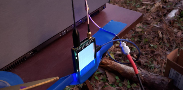
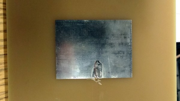
The process started with a set of calculations to derive the patch dimensions and a bit of PCB work adding a stripline feed. This was produced on a PCB, a normal 1.6mm thick FR4 fiberglass board. When hooked up to a VNA its impedance was all wrong. Further, it had a resonance at the required frequency but also unexpected ones at 3.7 and 4.6 GHz. Simulation of the design also yielded a different resonance from the one calculated, and discussing it with others yielded the conclusion that the feed might be at fault. He ended up using an inset feed, with a co-axial cable emerging away from the edge of the patch, and was able to achieve a far better result.

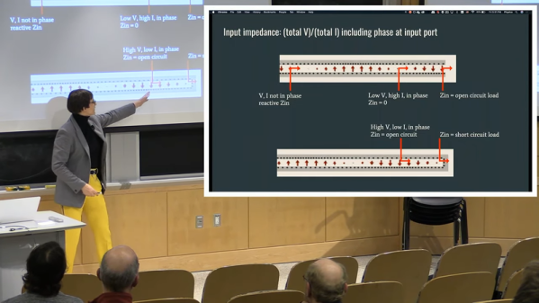
We can all learn something from [Adam]’s write-up, and we salute him for staying the course to get the design to a usable point. It would be interesting to see the same antenna produced from a more consistent dielectric material than generic FR4. Meanwhile, if you are interested in microwave RF design, take a look at Michael Ossmann’s primer on the subject.

DIY Radio Telescopes Hack Chat

Join us on Wednesday, February 12 at noon Pacific for the DIY Radio Telescopes Hack Chat with James Aguirre!

For most of history, astronomers were privy to the goings-on in the universe only in a very narrow slice of the electromagnetic spectrum. We had no idea that a vibrant and wondrous picture was being painted up and down the wavelengths, a portrait in radio waves of everything from nearly the moment of creation to the movement of galaxies. And all it took to listen in was an antenna and a radio receiver.

Over the years, radio telescopes have gotten more and more sophisticated and sensitive, and consequently bigger and bigger. We’re even to the point where one radio telescope often won’t cut it, and astronomers build arrays of telescopes spread over miles and miles, some with antennas that move around on rails. In the search for signals, radio astronomy has become the very definition of “Big Science.”

But radio astronomy doesn’t have to be big to be useful. James Aguirre, an astronomer at the University of Pennsylvania, spends his days (and nights) studying the radio universe with those big instruments. But he’s also passionate about down-scaling things and teaching everyone that small radio telescopes can be built on the cheap. His Mini Radio Telescope project uses a cast-off satellite TV dish and a couple of hundred bucks worth of readily available gear to scan the skies for all sorts of interesting phenomena.

Dr. Aguirre will join us on the Hack Chat to discuss all things radio astronomy, and how you can get in on the radio action on the cheap. Chances are good your junk pile — or your neighbor’s roof — has everything you need, and you might be surprised how approachable and engaging DIY radio astronomy can be.

join-hack-chatOur Hack Chats are live community events in the Hackaday.io Hack Chat group messaging. This week we’ll be sitting down on Wednesday, February 12 at 12:00 PM Pacific time. If time zones have got you down, we have a handy time zone converter.

Click that speech bubble to the right, and you’ll be taken directly to the Hack Chat group on Hackaday.io. You don’t have to wait until Wednesday; join whenever you want and you can see what the community is talking about. Continue reading “DIY Radio Telescopes Hack Chat”

Ham Antennas From MIT

Dealing with an antenna is one of those topics we never feel like we know enough about. MIT had a live stream of [Dr. Kiersten Kerby-Patel] discussing antennas in a talk, sponsored by the ham radio club on campus. You can see the recording below.

The main assertion of the presentation is that everything is a dipole unless it is a loop. Although the professor probably deals with antennas at an extremely high theoretical level, she did a great job of keeping it aimed at ham radio operators.

Continue reading “Ham Antennas From MIT”

NanoVNA Tests Antenna Pattern

When [Jephthai] wanted to build his own Yagi antenna, he turned to MMANA software for antenna modeling. This is an antenna analysis program that uses the moment method to calculate parameters for different antenna geometries. After building the Yagi, the predicted tuning and impedance matched the real antenna nicely. But what about the radiation pattern? To test that, he used a NanoVNA and a clever test setup.

He needed a test spot out of the antenna’s near field so he set up his workstation 18 feet away from the test antenna which was on a mount that could rotate. On the edge of the workstation table — affixed with painter’s tape — is a NanoVNA connected to a laptop.

Continue reading “NanoVNA Tests Antenna Pattern”

Weird World Of Microwaves Hack Chat

Join us on Wednesday, December 18 at noon Pacific for the Weird World of Microwaves Hack Chat with Shahriar Shahramian! We’ve been following him on The Signal Path for years and are excited to pick his brain on what is often considered one of the dark arts of electronics.

No matter how much you learn about electronics, there always seems to be another door to open. You think you know a thing or two once you learn about basic circuits, and then you discover RF circuits. Things start to get a little strange there, and stranger still as the wavelengths decrease and you start getting into the microwave bands. That’s where you see feed lines become waveguides, PCB traces act as components, and antennas that look more like musical instruments.

Shahriar is no stranger to this land. He’s been studying millimeter-wave systems for decades, and his day job is researching millimeter-wave ASICs for Nokia Bell Labs in New Jersey, the birthplace of the transistor. In his spare time, Shahriar runs The Signal Path, a popular blog and YouTube channel where he dives tear-downs, explanations, and repairs of incredibly sophisticated and often outrageously expensive equipment.

We’ll be sitting down with Shahriar this week for the last Hack Chat of 2019 with a peek inside his weird, wonderful world of microwaves. Join us with your questions about RF systems, microwaves in the communication industry, and perhaps even how he manages to find the gear featured on his channel.

join-hack-chatOur Hack Chats are live community events in the Hackaday.io Hack Chat group messaging. This week we’ll be sitting down on Wednesday, December 18 at 12:00 PM Pacific time. If time zones have got you down, we have a handy time zone converter.

Click that speech bubble to the right, and you’ll be taken directly to the Hack Chat group on Hackaday.io. You don’t have to wait until Wednesday; join whenever you want and you can see what the community is talking about.

Hacking Transmitters, 1920s Style

The origin of the term “breadboard” comes from an amusing past when wooden bread boards were swiped from kitchens and used as a canvas for radio hobbyists to roll homemade capacitors, inductors, and switches. At a period when commercial electronic components were limited, anything within reach was fair game.

[Andy Flowers], call sign K0SM, recently recreated some early transmitters using the same resources and techniques from the 1920s for the Bruce Kelley 1929 QSO Party. The style of the transmitters are based on [Ralph Hartley]’s oscillator circuit built for Bell Telephone in 1915. Most of the components he uses are from the time period, and one of the tubes he uses is even one of four tubes from the first Transatlantic contact in 1923.

Apart from vacuum tubes (which could be purchased) and meters (which could be scrounged from automobiles) [Flowers] recreated his own ferrite plate and outlet condensers for tuning the antennas. The spiderweb coils may not be as common today, but can be found in older Crosley receivers and use less wire than comparable cylindrical coils.

A number of others features of the transmitters also evoke period nostalgia. The coupling to the antenna can be changed using movable glass rods, although without shielding there are quite a number of factors to account for. A vertical panel in the 1920s style also shows measurements from the filament, plate current, and antenna coupling.

While amature radio has become increasingly high-tech over the last few years, it’s always good to see dedicated individuals keeping the old ways alive; no matter what kind of technology they’re interested in.

Continue reading “Hacking Transmitters, 1920s Style”

Incredibly Tiny RF Antennas For Practical Nanotech Radios

Researchers may have created the smallest-ever radio-frequency antennas, a development that should be of interest to any nanotechnology enthusiasts. A group of scientists from Korea published a paper in ACS Nano that details the fabrication of a two-dimensional radio-frequency antenna for wearable applications. Most antennas made from metallic materials like aluminum, cooper, or steel which are too thick to use for nanotechnology applications, even in the wearables space. The newly created antenna instead uses metallic niobium diselenide (NbSe2) to create a monopole patch RF antenna. Even with its sub-micrometer thickness (less than 1/100 the width of a strand of human hair), it functions effectively.

The metallic niobium atoms are sandwiched between two layers of selenium atoms to create the incredibly thin 2D composition. This was accomplished by spray-coating layers of the NbSe2 nanosheets onto a plastic substrate. A 10 mm x 10 mm patch of the material was able to perform with a 70.6% radiation efficiency, propagating RF signals in all directions. Changing the length of the antenna allowed its frequency to be tuned from 2.01-2.80 GHz, which includes the range required for Bluetooth and WiFi connectivity.

Within the ever-shrinking realm of sensors for wearable technologies, there is sure to be a place for tiny antennas as well.

[Thanks Qes for the tip!]