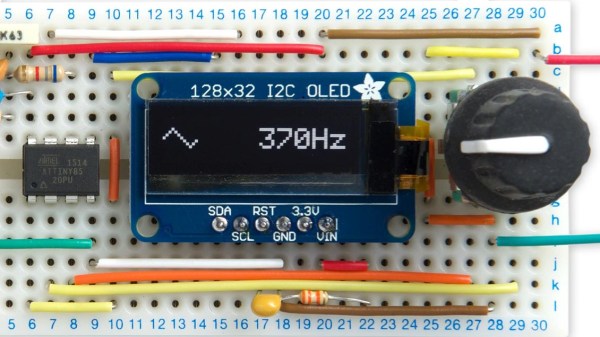
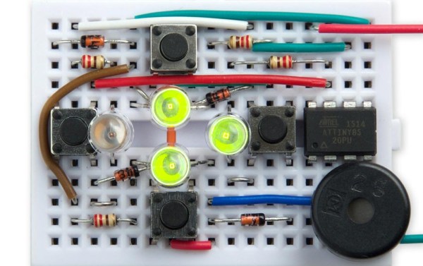
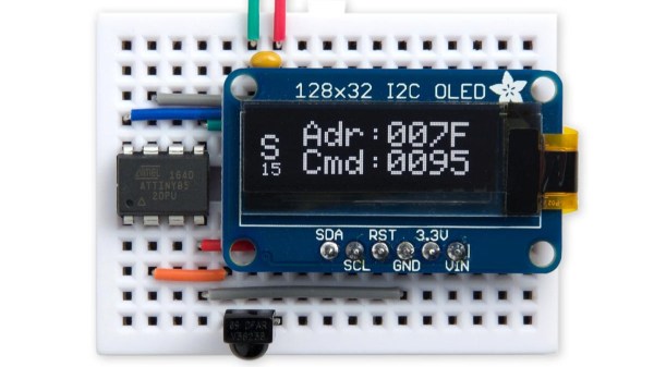
Environmentally Aware Jewelry Gets Attention

We didn’t include a “Most Ornate” category in this year’s Coin Cell Challenge, but if we had, the environmentally reactive jewelry created by [Maxim Krentovskiy] would certainly be the one to beat. Combining traditional jewelry materials with an Arduino-compatible microcontroller, RGB LEDs, and environmental sensors; the pieces are able to glow and change color based on environmental factors. Sort of like a “mood ring” for the microcontroller generation.

[Maxim] originally looked for a turn-key solution for his reactive jewelry project, but found that everything out there wasn’t quite what he was looking for. It was all either too big or too complicated. His list of requirements was relatively short and existing MCU boards were simply designed for more than what he needed.

On his 30 x 30 mm PCB [Maxim] has included the bare essentials to get an environmentally aware wearable up and running. Alongside the ATtiny85 MCU is a handful of RGB LEDs (with expansion capability to add more), as well as analog light and temperature sensors. With data from the sensors, the ATtiny85 can come up with different colors and blink frequencies for the LEDs, ranging from a randomized light show to a useful interpretation of the local environment.

It’s not much of a stretch to imagine practical applications for this technology. Consider a bracelet that starts flashing red when the wearer’s body temperature gets too high. Making assistive technology visually appealing is always a challenge, and there’s undoubtedly a market for pieces of jewelry that can communicate a person’s physical condition even when they themselves may be unable to.

Form or function, life saving or complete novelty, there’s still time to enter your own project in the 2017 Coin Cell Challenge.

Minimizing ESP8266 Battery Drain

[Alex Jensen] wanted to build a battery-powered weather station, using an ESP8266 breakout board to connect to WiFi. However, [Alex]’s research revealed that the ESP chip uses around 70mA per hour when the radio is on — meaning that he’d have to change batteries a lot more than he wanted to. He really wanted a low power rig such that he’d only have to change batteries every 2 years on a pair of AAs.

The two considerations would be, how often does the ESP get powered up for data transmissions — and how often the weather station’s ATtiny85 takes sensor readings. Waking up the ESP from sleep mode takes about 16mA — plus, once awake it takes about 3 seconds to reconnect, precious time at 70mA. However, by using a static IP address he was able to pare that down to half a second, with one more second to do the actual data transmission. In addition to the hourly WiFi connection, the Tiny85 must be powered, though its relatively modest 1.5mA per hour doesn’t amount to much, even with the chip awake for 36 hours during the year. All told, the various components came to around 500 mAh per year, so using a pair of AA batteries should keep the rig going for years.

We’re intrigued by stories of hackers eking out every last drop of power to make their projects work. We’ve posted about ESPs low-power mode before, and what can be more low-power than a watch running off a coin cell?

Continuity Tester Uses The ATtiny85’s Comparator

There’s an inside joke among cyclists – the number of bikes you need is “n+1”, where “n” is your current number of bikes. The same probably also applies to the number of tools and equipment a hacker needs on their workbench. Enough is never enough. Although [David Johnson-Davies] has a couple of multimeters lying around, he still felt the urge to build a stand-alone continuity tester and has posted details for a super-simple ATtiny85 based Continuity Tester on his blog. For a device this simple, he set himself some tall design goals. Using the ATtiny85 and a few SMD discretes, he built a handy tester that met all of his requirements and then some.

The ATtiny85’s Analog Comparator function is perfectly suited for such a tester. One input of the comparator is biased such that there is a 51 ohm resistor between the input and ground. The output of the comparator toggles when the resistance between the other input and ground is either higher or lower than 51 ohms. Enabling internal pullup resistors in the ATtiny85 not only takes care of proper biasing of the comparator pins, but also helps reduce current consumption when the ATtiny85 is put to sleep. The test current is limited to 100 μA, making the tester suitable for use in sensitive electronics. And enabling the sleep function after 60 seconds of inactivity reduces standby current to just about 1 μA, so there is no need for a power switch. [David] reckons the CR927 button cell ought to last pretty long.

For those interested in building this handy tester, [David] has shared the Eagle CAD files as well as the ATtiny85 code on his Github repository or you could just order out some boards from OSHpark.

Snail Is Actually Cleverly Strange Geocaching Waypoint

Basic geocaching consists of following GPS coordinates to a location, then finding a container which is concealed somewhere nearby. Like any activity, people tend to add their own twists to keep things interesting. [Jangeox] recently posted a video of the OLED Snail 2.0 to show off his most recent work. (This is a refinement of an earlier version, which he describes in a blog post.)

Another of [Jangeox]’s Electronic Waypoints
[Jangeox] spices up geocaching by creating electronic waypoints, and the OLED Snail is one of these. Instead of GPS coordinates sending someone directly to a goal, a person instead finds a waypoint that reveals another set of coordinates and these waypoints are followed like a trail of breadcrumbs.

A typical waypoint is an ATTINY85 microcontroller programmed to display an animated message on the OLED, and the message reveals the coordinates to the next waypoint. The waypoint is always cleverly hidden, and in the case of the OLED Snail 2.0 the enclosure is the shell of a large snail containing the electronics encased in resin. This means that the devices have a finite lifespan — the battery sealed inside is all the power the device gets. Fortunately, with the help of a tilt switch the electronics can remain dormant until someone picks it up to start the show. Other waypoints have included a fake plant, and the fake bolt shown here. Video of the OLED Snail 2.0 is embedded below.

Continue reading “Snail Is Actually Cleverly Strange Geocaching Waypoint”

ESP8266 As A Tape Drive

1976 was the year the Apple I was released, one of several computers based on the MOS 6502 chip. MOS itself released the KIM-1 (Keyboard Input Monitor) initially to demonstrate the power of the chip. The single board computer had two connectors on it, one of which could be used for a tape recorder for long-term storage. When [Willem Aandewiel] went to the Apple Museum Nederland in 2016, he saw one and felt nostalgic for his youth. He was able to get a replica, the microKIM, and build it but he wanted to use new technology to interface with this old technology, so he decided to use an ESP8266 as a solid state tape recorder.

One of the reasons the KIM-1 was so popular when it was released was that there was lots of documentation available. [Willem] used this documentation to figure out how the KIM-1 saves data to the recording device. An ATTiny85 is used to decode the pulse stream that the KIM-1 sends when saving because the timing was too tight to both “listen” and decode the bits as well as convert and store them. For loading programs, the data can be sent digitally as 1’s and 0’s to the KIM-1. This means that the ATTiny is only used for decoding and doesn’t have to re-encode the data.  Because of this, saving is slow, but loading is very quick.

To complete the project, [Willem] added four buttons, one each for rewind, record, play and fast-forward, and a screen so you can see which program is currently selected and can go from one program to another. As a nice throwback touch, record and play have to be pressed at the same time when saving. For more 6502 projects, check out this 6502 based DIY computer, or this 6502 built from discrete parts.

Continue reading “ESP8266 As A Tape Drive”

DIY Pyrography Power Supply

Ever wanted to try your hand at wood burning? If you already threw away your first soldering iron—you know the one: plugged straight in to the wall, no temperature control, came with a thick piece of tin foil to rest it on—don’t despair. Pyrography pens don’t cost that much. The variable power supply they plug into, though: that’s another story. Those cost more than they probably should.

[td0g] took the plunge into pyrography a while back, and wanted to build his own controller from an old ATX power supply. Why not? It should be more than capable of doing the job. Even the most heavy-duty pyrography pens only draw 10A, and the 3.3V line showed to be rated for 30A. All [td0g] had to do was add a PWM with a MOSFET and a ‘Tiny85.

The project nearly became Fail of the Week fodder after [td0g] saw huge voltage spikes across the MOSFET. A 47kΩ resistor took care of those, and a heat sink salvaged from the junk bin will prolong the transistor’s life. [td0g] added a push button that cycles through five heat settings, and an LED to show the status. After that, all he had to do was add a male RCA input to connect the pens he already has.

Okay, so you wouldn’t be caught dead dropping money on some fancy power supply for this new hobby. Don’t want to buy pens, either? Roll your own from a plasma arc lighter.

LAMEBOY Is Handheld Gaming On The ESP8266

We’ve had our eye on [davedarko’s] LAMEBOY project for a while now, a handheld setup in roughly the same form factor as the classic Nintendo Game Boy. It’s remarkable how approachable portable electronic design has become, and that’s really what makes this interesting. The design is beautiful, and the closer you look, the more respect you have for what [dave] is doing.

Right now his proof of concept has a 3D printed enclosure whose face is the printed circuit board. We love how the lower left corner of the PCB slips under a pocket in the case, which makes it possible to use just one screw to secure the two together in the upper right.

The LAMEBOY is built around an ESP8266 module. Anyone who has used one knows this chip contains a fair amount of horsepower, but very little I/O. [Dave] has a lot going on with an LCD screen, six user buttons, a USB to I/O chip, and an SD card slot. He took two approaches to solve this dilemma. First he grabbed a PCF8574 port expander, and second he’s offloaded the color control of the screen backlights to an ATtiny85 (running a BlinkM clone).

Below you can see some early game tests on the perfboard prototype. We haven’t seen game play on the most recent prototype (there is a screen color test video in his latest project log) but it sounds as though [dave] plans to make use of the Gamebuino framework. This should mean that there will be no shortage of cool ROMs to load.

Continue reading “LAMEBOY Is Handheld Gaming On The ESP8266”