If we say that a hacker is somebody who looks at a “solved” problem and can still come up with multiple alternative solutions, then [Charles Ouweland] absolutely meets the grade. Not that we needed more evidence of his hacker cred given what we’ve seen from him before, but he recently wrote in to tell us about an interesting bit of problem solving which we think is a perfect example of the principle. He wanted to drive a salvaged seven segment LED display with an AVR microcontroller, but there was only one problem: the display needs 15V but the AVR is only capable of 5V. So what to do?
 As it turns out, the first step to solving the problem was verifying there was actually a problem to begin with. [Charles] did some experimentation and found that the display didn’t actually need 15V to operate, and in fact would light up well enough at just 6.5V. This lowered the bar quite a bit, but it was still too high to power directly from the chip.
There were a few common ways to solve this problem, which no doubt the Hackaday reader is well aware of. But [Charles] wanted to take the path less traveled. More specifically, the path with the least amount of additional components he had to put on his PCB. He set out to find the absolute easiest way to make his 5V AVR light up a 6.5V LED, and ended up coming with a very clever solution that some may not even know is possible.
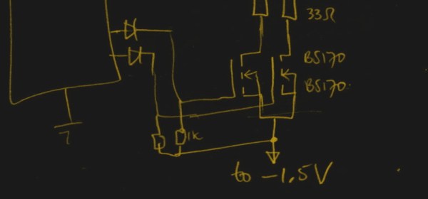
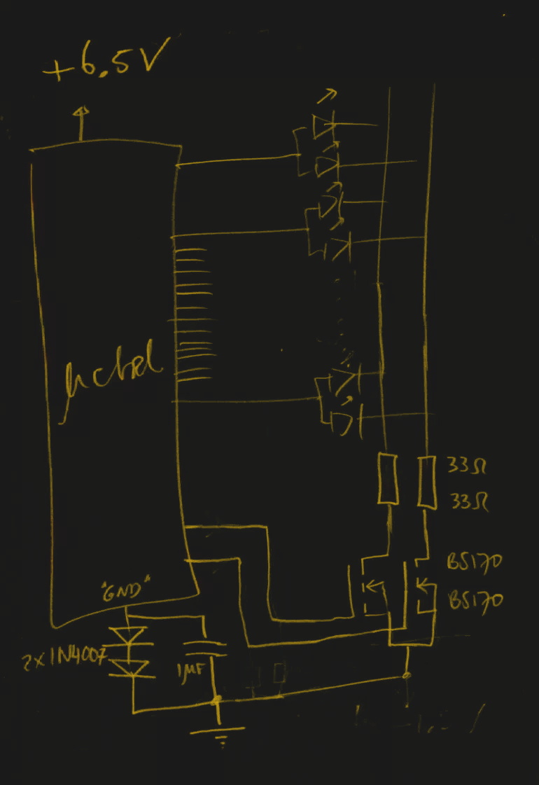
He reasoned that if he connected the source pins of two BS170 MOSFETs to a voltage of -1.5V, even when the AVR pin was 0V, they would be still be receiving 1.5V. This virtual “step ladder” meant that once the AVR’s pin goes high (5V), the relative voltage would actually be 6.5V and enough to drive his LEDs. Of course the only problem with that is that you need to have a source for -1.5V.
Getting a negative voltage would normally require adding more components to the design (which he set out to avoid in the first place), but then he came up with another clever idea. To pull the trick off, he actually feeds the AVR 6.5V, but raises the ground voltage by 1.5V with the addition of two 1N4007 diodes. This way the AVR gets a voltage within its capabilities and still can provide a relative 6.5V to the LEDs.
One might say [Charles] took the Kobayashi Maru approach, and simply redefined the rules of the game. But such is the power of the confounding negative voltage.